
Fundamentals of Electric Circuits
6th Edition
ISBN: 9780078028229
Author: Charles K Alexander, Matthew Sadiku
Publisher: McGraw-Hill Education
expand_more
expand_more
format_list_bulleted
Videos
Textbook Question
Chapter 6, Problem 61P
Consider the circuit in Fig. 6.83. Find: (a) Leq, i1(t), and i2(t) if is = 3e−t mA, (b) vo(t), (c) energy stored in the 20-mH inductor at t = 1 s.
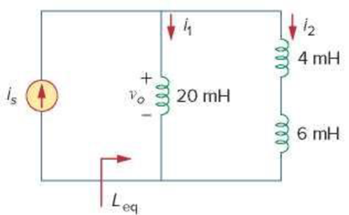
Figure 6.83
For Prob. 6.61.
Expert Solution & Answer
Want to see the full answer?
Check out a sample textbook solution
Students have asked these similar questions
Design a traffic light PIC microcontroller program with
Green LED has 3 Sec
Yellow LED has 0.5 Sec
Red LED has 3 Sec
RASAN4SSC20UT
8
RBOINT
RB1
9
RB2
U1
PIC16F877A-I/PT
18
19
MCLRVPP
RAOANO
20
RA1AN1
30 OSCICLKI
21
RAZAN2VREF-CVREF
31 OSC2CLKO
RABAN3VREF+ 22
LED1
LED-3MM
〃
R1
330
RA4TOCKIC1OUT 23
7 VDD
28
VDD
6
VSS
29
VSS
24
LED2
LED-3MM
R2
10
330
RB3PGM
11
+
14
RB4
38
RDOPSPO
RB5 15
LED3
39
RD1PSP1
40
RD2PSP2
RB6PGC-
RB7PGD 17
16
LED-3MM
R3
330
41
RD3PSP3
2
RD4PSP4
RCOT1OSOTICKK
3
RDSPSPS
RC1T10SICCP24
RD6PSP6
RC2CCP1
5
RD7PSP7
RC3SCKSCL
RC4SDISDA
25
REORDANS
RCSSDO
27
29 REIWRANG
RC6TXCK-
RE2CSAN7
RC7RXDT
DAWWWW
32
35
36
37
42
43
44
1
12
NO
13
NC
33
NO
34
NC
: +0
العنوان
I need a detailed drawing with explanation
しじ
ined sove in peaper
Anoting
Q4// Draw and Evaluate √√√xy-²sin(y²)dydx
PU+96er
Lake
Ge
Q3// Find the volume of the region between the cylinder 2 = y² and the xy-
plane that is bounded by the planes x = 1, x = 2, y = -2, and y = 2.
T
M
Find Va and Vb using Mesh analysis
Chapter 6 Solutions
Fundamentals of Electric Circuits
Ch. 6.2 - What is the voltage across a 4.5-F capacitor if...Ch. 6.2 - If a 10-F capacitor is connected to a voltage...Ch. 6.2 - The current through a 100-F capacitor is i(t) = 50...Ch. 6.2 - Figure 6.11 For Practice Prob. 6.4. An initially...Ch. 6.2 - Under dc conditions, find the energy stored in the...Ch. 6.3 - Find the equivalent capacitance seen at the...Ch. 6.3 - Find the voltage across each of the capacitors in...Ch. 6.4 - If the current through a 1-mH inductor is i(t) =...Ch. 6.4 - The terminal voltage of a 2-H inductor is v = 10(1...Ch. 6.4 - Determine vC, iL, and the energy stored in the...
Ch. 6.5 - Calculate the equivalent inductance for the...Ch. 6.5 - In the circuit of Fig. 6.34, i1(t) = 3e2t A. If...Ch. 6.6 - The integrator in Fig. 6.35(b) has R = 100 k, C =...Ch. 6.6 - The differentiator in Fig. 6.37 has R = 100 k and...Ch. 6.6 - Design an analog computer circuit to solve the...Ch. 6 - What charge is on a 5-F capacitor when it is...Ch. 6 - Capacitance is measured in: (a)coulombs (b)joules...Ch. 6 - When the total charge in a capacitor is doubled,...Ch. 6 - Can the voltage waveform in Fig. 6.42 be...Ch. 6 - The total capacitance of two 40-mF...Ch. 6 - In Fig. 6.43, if i = cos 4t and v = sin 4t, the...Ch. 6 - A 5-H inductor changes its current by 3 A in 0.2...Ch. 6 - If the current through a 10-mH inductor increases...Ch. 6 - Inductors in parallel can be combined just like...Ch. 6 - Prob. 10RQCh. 6 - If the voltage across a 7.5-F capacitor is 2te3t...Ch. 6 - A 50-F capacitor has energy w(t) = 10 cos2 377t J....Ch. 6 - Design a problem to help other students better...Ch. 6 - A voltage across a capacitor is equal to [2 2...Ch. 6 - The voltage across a 4-F capacitor is shown in...Ch. 6 - The voltage waveform in Fig. 6.46 is applied...Ch. 6 - At t = 0, the voltage across a 25-mF capacitor is...Ch. 6 - A 4-mF capacitor has the terminal voltage v=...Ch. 6 - The current through a 0.5-F capacitor is 6(1 et)...Ch. 6 - The voltage across a 5-mF capacitor is shown in...Ch. 6 - A 4-mF capacitor has the current waveform shown in...Ch. 6 - A voltage of 45e2000t V appears across a parallel...Ch. 6 - Find the voltage across the capacitors in the...Ch. 6 - Series-connected 20- and 60-pF capacitors are...Ch. 6 - Two capacitors (25 and 75 F) are connected to a...Ch. 6 - The equivalent capacitance at terminals a-b in the...Ch. 6 - Determine the equivalent capacitance for each of...Ch. 6 - Find Ceq in the circuit of Fig. 6.52 if all...Ch. 6 - Find the equivalent capacitance between terminals...Ch. 6 - Find the equivalent capacitance at terminals a-b...Ch. 6 - Determine the equivalent capacitance at terminals...Ch. 6 - Obtain the equivalent capacitance of the circuit...Ch. 6 - Using Fig. 6.57, design a problem that will help...Ch. 6 - In the circuit shown in Fig. 6.58 assume that the...Ch. 6 - (a)Show that the voltage-division rule for two...Ch. 6 - Three capacitors, C1 = 5 F, C2 = 10 F, and C3 = 20...Ch. 6 - Given that four 10-F capacitors can be connected...Ch. 6 - Obtain the equivalent capacitance of the network...Ch. 6 - Determine Ceq for each circuit in Fig. 6.61....Ch. 6 - Assuming that the capacitors are initially...Ch. 6 - If v(0) = 0, find v(t), i1(t), and i2(t) in the...Ch. 6 - In the circuit in Fig. 6.64, let is = 4.5e2t mA...Ch. 6 - Obtain the Thevenin equivalent at the terminals,...Ch. 6 - The current through a 25-mH inductor is 10et/2 A....Ch. 6 - An inductor has a linear change in current from...Ch. 6 - Design a problem to help other students better...Ch. 6 - The current through a 12-mH inductor is 4 sin 100t...Ch. 6 - The current through a 40-mH inductor is i(t)= 0,...Ch. 6 - The voltage across a 50-mH inductor is given by...Ch. 6 - The current through a 5-mH inductor is shown in...Ch. 6 - The voltage across a 2-H inductor is 20(1 e2t) V....Ch. 6 - If the voltage waveform in Fig. 6.67 is applied...Ch. 6 - The current in a 150-mH inductor increases from 0...Ch. 6 - A 100-mH inductor is connected in parallel with a...Ch. 6 - If the voltage waveform in Fig. 6.68 is applied to...Ch. 6 - Find vC, iL, and the energy stored in the...Ch. 6 - For the circuit in Fig. 6.70, calculate the value...Ch. 6 - Under steady-state dc conditions, find i and v in...Ch. 6 - Find the equivalent inductance of the circuit in...Ch. 6 - An energy-storage network consists of...Ch. 6 - Determine Leq at terminals a-b of the circuit in...Ch. 6 - Using Fig. 6.74, design a problem to help other...Ch. 6 - Find Leq at the terminals of the circuit in Fig....Ch. 6 - Find the equivalent inductance looking into the...Ch. 6 - Find Leq in each of the circuits in Fig. 6.77....Ch. 6 - Find Leq in the circuit of Fig. 6.78. Figure 6.78...Ch. 6 - Determine Leq that may be used to represent the...Ch. 6 - The current waveform in Fig. 6.80 flows through a...Ch. 6 - (a) For two inductors in series as in Fig....Ch. 6 - In the circuit of Fig. 6.82, io(0) = 2 A....Ch. 6 - Consider the circuit in Fig. 6.83. Find: (a) Leq,...Ch. 6 - Consider the circuit in Fig. 6.84. Given that v(t)...Ch. 6 - In the circuit of Fig. 6.85, sketch vo. Figure...Ch. 6 - The switch in Fig. 6.86 has been in position A for...Ch. 6 - The inductors in Fig. 6.87 are initially charged...Ch. 6 - The current i(t) through a 20-mH inductor is...Ch. 6 - An op amp integrator has R = 50 k and C = 0.04 F....Ch. 6 - A 6-V dc voltage is applied to an integrator with...Ch. 6 - An op amp integrator with R = 4 M and C = 1 F has...Ch. 6 - Using a single op amp, a capacitor, and resistors...Ch. 6 - Show how you would use a single op amp to generate...Ch. 6 - At t = 1.5 ms, calculate vo due to the cascaded...Ch. 6 - Show that the circuit in Fig. 6.90 is a...Ch. 6 - The triangular waveform in Fig. 6.91(a) is applied...Ch. 6 - An op amp differentiator has R = 250 k and C = 10...Ch. 6 - A voltage waveform has the following...Ch. 6 - The output vo of the op amp circuit in Fig....Ch. 6 - Prob. 78PCh. 6 - Figure 6.93 presents an analog computer designed...Ch. 6 - Design an analog computer to simulate the...Ch. 6 - Design an op amp circuit such that vo=10vs+2vsdt...Ch. 6 - Your laboratory has available a large number of...Ch. 6 - An 8-mH inductor is used in a fusion power...Ch. 6 - A square-wave generator produces the voltage...Ch. 6 - An electric motor can be modeled as a series...
Knowledge Booster


Learn more about
Need a deep-dive on the concept behind this application? Look no further. Learn more about this topic, electrical-engineering and related others by exploring similar questions and additional content below.Similar questions
- Please solve this question step by step and handwritten and do not use chat gpt or ai tools thank you very much!arrow_forwardPlease solve question c and d step by step and handwritten and do not use chat gpt or ai tools thank you very much!arrow_forwardPlease solve questions d,e,f step by step and handwritten and do not use chat gpt or ai tools thank you very much!arrow_forward
- Please solve this question step by step and handwritten and do not use chat gpt or ai tools thank you very much!arrow_forwardPlease solve question c,d,e step by step and handwritten and do not use chat gpt or ai tools thank you very much!arrow_forwardQ1: Design a logic circuit for the finite-state machine described by the assigned table in Fig. 1: Using D flip-flops. a. b. Using T flip-flops. Present Next State Output State x=0 x=0 YE Y₁Y Y₁Y Z 00 00 01 0 0 от 00 0 0 10 00 10 11 00 10 0arrow_forward
arrow_back_ios
SEE MORE QUESTIONS
arrow_forward_ios
Recommended textbooks for you
 Introductory Circuit Analysis (13th Edition)Electrical EngineeringISBN:9780133923605Author:Robert L. BoylestadPublisher:PEARSON
 Delmar's Standard Textbook Of ElectricityElectrical EngineeringISBN:9781337900348Author:Stephen L. HermanPublisher:Cengage Learning
 Programmable Logic ControllersElectrical EngineeringISBN:9780073373843Author:Frank D. PetruzellaPublisher:McGraw-Hill Education
 Fundamentals of Electric CircuitsElectrical EngineeringISBN:9780078028229Author:Charles K Alexander, Matthew SadikuPublisher:McGraw-Hill Education
 Electric Circuits. (11th Edition)Electrical EngineeringISBN:9780134746968Author:James W. Nilsson, Susan RiedelPublisher:PEARSON
 Engineering ElectromagneticsElectrical EngineeringISBN:9780078028151Author:Hayt, William H. (william Hart), Jr, BUCK, John A.Publisher:Mcgraw-hill Education,
Introductory Circuit Analysis (13th Edition)
Electrical Engineering
ISBN:9780133923605
Author:Robert L. Boylestad
Publisher:PEARSON
Delmar's Standard Textbook Of Electricity
Electrical Engineering
ISBN:9781337900348
Author:Stephen L. Herman
Publisher:Cengage Learning
Programmable Logic Controllers
Electrical Engineering
ISBN:9780073373843
Author:Frank D. Petruzella
Publisher:McGraw-Hill Education
Fundamentals of Electric Circuits
Electrical Engineering
ISBN:9780078028229
Author:Charles K Alexander, Matthew Sadiku
Publisher:McGraw-Hill Education
Electric Circuits. (11th Edition)
Electrical Engineering
ISBN:9780134746968
Author:James W. Nilsson, Susan Riedel
Publisher:PEARSON
Engineering Electromagnetics
Electrical Engineering
ISBN:9780078028151
Author:Hayt, William H. (william Hart), Jr, BUCK, John A.
Publisher:Mcgraw-hill Education,
Inductors Explained - The basics how inductors work working principle; Author: The Engineering Mindset;https://www.youtube.com/watch?v=KSylo01n5FY;License: Standard Youtube License