Videos
The switch in the bottom loop of Fig. P6.1 is closed at t = 0 and then opened at a later time t1. What is the direction of the current I in the top loop (clockwise or counterclockwise) at each of these two times?
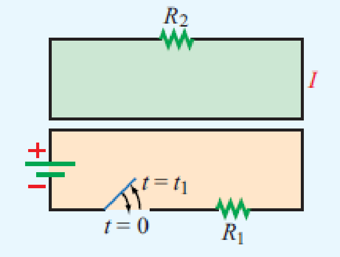
Figure P6.1 Loops of Problem 6.1.
The direction of the current
Answer to Problem 1P
The current in the top loop will be in counter-clockwise direction.
Explanation of Solution
Given data:
The required diagram is drawn as shown in Figure 1.
Calculation:
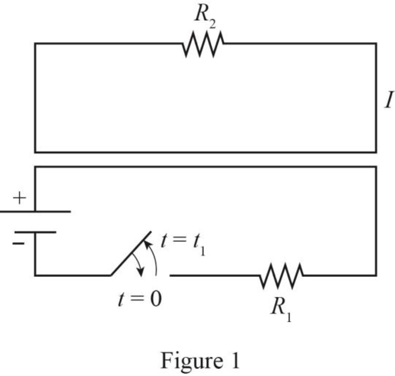
The required diagram is drawn as shown in Figure 2 at
It is observed that at
Hence, the current in the top loop is also momentarily clockwise direction.
From Figure 1, it is observed that there is no current flow in the bottom loop because switch is open. Due to this, there is a decrement of the flux in the secondary loop and if flux decreases then the direction of current will be reversed.
Hence, the current in the top loop will be in counter-clockwise direction.
Conclusion:
Therefore, the current in the top loop will be in counter-clockwise direction.
Want to see more full solutions like this?
Chapter 6 Solutions
EBK FUNDAMENTALS OF APPLIED ELECTROMAGN
Additional Engineering Textbook Solutions
Java: An Introduction to Problem Solving and Programming (8th Edition)
Concepts Of Programming Languages
Electric Circuits. (11th Edition)
Database Concepts (8th Edition)
Introduction To Programming Using Visual Basic (11th Edition)
Starting Out with Python (4th Edition)


- Can you draw the computed panel board (2nd attached pic) like the panel board management (1st attached pic)? ps. not graded, i just want to know what it looks like when it draw.arrow_forwardFor the circuit shown, let Is = 5, R₁-40, R2-30, R3-100, R4-80, R5-40, R6-30, R7- 10, and Rg= 100, and find: R₂ R6 ww www VX R3 R7 R8 RI R₁₂ Rs R5 www • The voltage Vx" (V) ⚫ The power absorbed by the output resistor Rg: Power= {Hint: you can use current divider (CD) or any other method.} (W) Tarrow_forwardFor the circuit shown, let V₁ = 26, R1-30, R₂-40, R3-50, R4-20, R5-100, R6-10, and find: RA R5 R3 V (+) R₁ R₂ R6 www • The voltage v (V) • The power delivered by the power source Vs: Power= {Hint: you can use voltage divider (VD) or any other method.} (W)arrow_forward
- In the circuit shown, let R₁-7, R₂-12, R3-24, R4-2, V₁ =17, V2 -68, and V3-51, to calculate the power delivered (or absorbed) by the circuit inside the box, as follows: {NOTE: On Multiple Choice Questions, like this problem, you have only one attempt } 1. The current I is equal to (choose the closed values in amperes) -0.791 0 -0.756 3.022 0.756 (A) -3.022 0.791 2. The power delivered (or absorbed) (choose the closest value in watts) (W) 373.345 0 -373.345 -52.234 52.234 65.079 O-24.833 R₁ V₂ R3 R₂ www V3 V₁ www R4arrow_forwardDetermine X(w) for the given function shown in Figure (1) by applying the differentiation property of the Fourier Transform. x(t) Figure (1) -2 -1 1 2arrow_forwardFor a enahnced-type NMOS transistor with V₁=+1V and kn'(w/L)= 2 mA/V2, find the minimum VDs required to operate in the saturation region when VGS=+2 V. What is the corresponding value of ID?arrow_forward
- . Using Properties to find the Z-Transform including the region of convergence for x(n) = n (2)" cos(0.2π(n − 2))u(n − 1) - -arrow_forwardJ VDD M₁ In the circuit of figure shown below, determine the region of operation of M₁as Vigoes from VDD.to zero. (You may want to draw a plot or just explain by the range, remember the transistor is a PMOS) Assume VDD = 2.5 V and | VTH | = 0.4V. 5 + 1 Varrow_forwardWe wish to design the circuit of the figure shown below for a drain current of 1 mA (l=1mA). If W/L = 18/0.18, compute R1 and R2 such that the input impedance is at least 20 k. R₁ VDD = 1.8 V 500 Ω M₁ R₂arrow_forward
 Introductory Circuit Analysis (13th Edition)Electrical EngineeringISBN:9780133923605Author:Robert L. BoylestadPublisher:PEARSON
 Delmar's Standard Textbook Of ElectricityElectrical EngineeringISBN:9781337900348Author:Stephen L. HermanPublisher:Cengage Learning
 Programmable Logic ControllersElectrical EngineeringISBN:9780073373843Author:Frank D. PetruzellaPublisher:McGraw-Hill Education
 Fundamentals of Electric CircuitsElectrical EngineeringISBN:9780078028229Author:Charles K Alexander, Matthew SadikuPublisher:McGraw-Hill Education
 Electric Circuits. (11th Edition)Electrical EngineeringISBN:9780134746968Author:James W. Nilsson, Susan RiedelPublisher:PEARSON
 Engineering ElectromagneticsElectrical EngineeringISBN:9780078028151Author:Hayt, William H. (william Hart), Jr, BUCK, John A.Publisher:Mcgraw-hill Education,