EBK FUNDAMENTALS OF APPLIED ELECTROMAGN
7th Edition
ISBN: 8220100663659
Author: ULABY
Publisher: PEARSON
expand_more
expand_more
format_list_bulleted
Concept explainers
Textbook Question
Chapter 6, Problem 6P
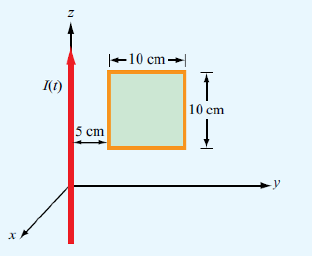
The square loop shown in Fig. P6.6 is coplanar with a long, straight wire carrying a current
I (t) = 5 cos(2π × 104t) (A).

- (a) Determine the emf induced across a small gap created in the loop.
- (b) Determine the direction and magnitude of the current that would flow through a 4 Ω resistor connected across the gap. The loop has an internal resistance of 1 Ω.
Expert Solution & Answer
Want to see the full answer?
Check out a sample textbook solution
Students have asked these similar questions
Find Laplace inverse for
-25
-1
e
S-1
This question and its solution. Is the solution correct? If the solution is correct, assume that let R2 = 20 and a=500 . If it is wrong, solve it in your own way, away from the sources, and explain to me in detail with a pen and paper, please.
can you compute the values inside the blue circles using the data from the plan above them? Please disregard the values (data/numbers) inside the circles.
Chapter 6 Solutions
EBK FUNDAMENTALS OF APPLIED ELECTROMAGN
Ch. 6.2 - Explain Faradays law and the function of Lenzs...Ch. 6.2 - Prob. 2CQCh. 6.2 - Prob. 3CQCh. 6.2 - For the loop shown in Fig. 6-3, what is Vemftr if...Ch. 6.2 - Suppose that the loop of Example 6-1 is replaced...Ch. 6.4 - Suppose that no friction is involved in sliding...Ch. 6.4 - Is the current flowing in the rod of Fig. 6-10 a...Ch. 6.4 - For the moving loop of Fig. 6-9, find I when the...Ch. 6.4 - Suppose that we turn the loop of Fig. 6-9 so that...Ch. 6.5 - Contrast the operation of an ac motor with that of...
Ch. 6.5 - Prob. 7CQCh. 6.5 - Prob. 8CQCh. 6.7 - A poor conductor is characterized by a...Ch. 6.8 - When conduction current flows through a material,...Ch. 6.8 - Verify that the integral form of Ampres law given...Ch. 6.10 - Explain how the charge continuity equation leads...Ch. 6.10 - How long is the relaxation time constant for...Ch. 6.10 - Determine (a) the relaxation time constant and (b)...Ch. 6.11 - Prob. 7ECh. 6 - The switch in the bottom loop of Fig. P6.1 is...Ch. 6 - The loop in Fig. P6.2 is in the xy plane and B =...Ch. 6 - A coil consists of 100 turns of wire wrapped...Ch. 6 - A stationary conducting loop with an internal...Ch. 6 - A circular-loop TV antenna with 0.02 m2 area is in...Ch. 6 - The square loop shown in Fig. P6.6 is coplanar...Ch. 6 - The rectangular conducting loop shown in Fig. P6.7...Ch. 6 - Prob. 8PCh. 6 - Prob. 9PCh. 6 - A 50 cm long metal rod rotates about the z axis at...Ch. 6 - The loop shown in P6.11 moves away from a wire...Ch. 6 - The electromagnetic generator shown in Fig. 6-12...Ch. 6 - The circular, conducting, disk shown in Fig. P6.13...Ch. 6 - The plates of a parallel-plate capacitor have...Ch. 6 - A coaxial capacitor of length l = 6 cm uses an...Ch. 6 - The parallel-plate capacitor shown in Fig. P6.16...Ch. 6 - In wet soil, characterized by = 102 (S/m), r = 1,...Ch. 6 - An electromagnetic wave propagating in seawater...Ch. 6 - At t = 0, charge density v0 was introduced into...Ch. 6 - If the current density in a conducting medium is...Ch. 6 - Prob. 21PCh. 6 - If we were to characterize how good a material is...Ch. 6 - The electric field of an electromagnetic wave...Ch. 6 - The magnetic field in a dielectric material with ...Ch. 6 - Given an electric field E=xE0sinaycos(tkz), where...Ch. 6 - The electric field radiated by a short dipole...Ch. 6 - A Hertzian dipole is a short conducting wire...Ch. 6 - In free space, the magnetic field is given by...Ch. 6 - The magnetic field in a given dielectric medium is...
Knowledge Booster
Learn more about
Need a deep-dive on the concept behind this application? Look no further. Learn more about this topic, electrical-engineering and related others by exploring similar questions and additional content below.Similar questions
- The average output voltage is found from Vac = = 2 2π/6 3√3 π -V #16 m √√3V™ cos ot d (ot) 0 = 1.654Vm m where Vm, is the peak phase voltage. I want detailed integration steps and how you reached this result.arrow_forwardHow would you solve this question using nodal analysis?arrow_forwardFor the circuit, calculate Vr. Calculate the threshold input voltage Vi that will change the output of the comparator from high to low. Show all calculations and explain your work.arrow_forward
- I need expert solutions to thisarrow_forwardARD1 Reset BTN OOOOOO RESET +5V Gnd Gnd Vin 10 PC0/ADCO A1 PC1/ADC1 A2 ANALOG IN PC2/ADC2 A3 PC3/ADC3 4 PC4/ADC4/SDA A5 PC5/ADC5/SCL ARDUINO UNO ON ATMEGA328P PU AREF 13 PB5/SCK 12 PB4/MISO 11 ~ PB3/MOSI/OC2A ~ PB2/OC1B 10 9 - PB1/OC1A PB0/ICP1/CLKO 8 PD7/AIN1 ~ PD7/AIN1 5 ~ PD5/T1/OC0B ~ PD3/INT1/OC2B 4 PD4/T0/XCK 3 2 PD2/INTO PD1/TXD 0 PDO/RXDarrow_forwardPls show neat and whole solutionarrow_forward
- help on this question about electrical machinery?arrow_forwardSolve the homework in a realistic way in more than one way with paper and pen without artificial intelligencearrow_forwardA 460 V 25 HP 4 poles connected in Y wound rotor induction motor has the following parameters: R1 = 0.641 ohms, X1 = 1.106 ohms, R2 = 0.332 ohms, X2 = 0.464 ohms and Xm = 26.3 ohms. For this machine calculate the maximum torque, rotation and corresponding slip.arrow_forward
arrow_back_ios
SEE MORE QUESTIONS
arrow_forward_ios
Recommended textbooks for you
 Introductory Circuit Analysis (13th Edition)Electrical EngineeringISBN:9780133923605Author:Robert L. BoylestadPublisher:PEARSON
 Delmar's Standard Textbook Of ElectricityElectrical EngineeringISBN:9781337900348Author:Stephen L. HermanPublisher:Cengage Learning
 Programmable Logic ControllersElectrical EngineeringISBN:9780073373843Author:Frank D. PetruzellaPublisher:McGraw-Hill Education
 Fundamentals of Electric CircuitsElectrical EngineeringISBN:9780078028229Author:Charles K Alexander, Matthew SadikuPublisher:McGraw-Hill Education
 Electric Circuits. (11th Edition)Electrical EngineeringISBN:9780134746968Author:James W. Nilsson, Susan RiedelPublisher:PEARSON
 Engineering ElectromagneticsElectrical EngineeringISBN:9780078028151Author:Hayt, William H. (william Hart), Jr, BUCK, John A.Publisher:Mcgraw-hill Education,

Introductory Circuit Analysis (13th Edition)
Electrical Engineering
ISBN:9780133923605
Author:Robert L. Boylestad
Publisher:PEARSON

Delmar's Standard Textbook Of Electricity
Electrical Engineering
ISBN:9781337900348
Author:Stephen L. Herman
Publisher:Cengage Learning

Programmable Logic Controllers
Electrical Engineering
ISBN:9780073373843
Author:Frank D. Petruzella
Publisher:McGraw-Hill Education

Fundamentals of Electric Circuits
Electrical Engineering
ISBN:9780078028229
Author:Charles K Alexander, Matthew Sadiku
Publisher:McGraw-Hill Education

Electric Circuits. (11th Edition)
Electrical Engineering
ISBN:9780134746968
Author:James W. Nilsson, Susan Riedel
Publisher:PEARSON

Engineering Electromagnetics
Electrical Engineering
ISBN:9780078028151
Author:Hayt, William H. (william Hart), Jr, BUCK, John A.
Publisher:Mcgraw-hill Education,
Capacitors Explained - The basics how capacitors work working principle; Author: The Engineering Mindset;https://www.youtube.com/watch?v=X4EUwTwZ110;License: Standard YouTube License, CC-BY