EBK FUNDAMENTALS OF APPLIED ELECTROMAGN
7th Edition
ISBN: 8220100663659
Author: ULABY
Publisher: PEARSON
expand_more
expand_more
format_list_bulleted
Concept explainers
Videos
Textbook Question
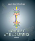
Chapter 6, Problem 11P
The loop shown in P6.11 moves away from a wire carrying a current I1 = 10 A at a constant velocity
Expert Solution & Answer
Want to see the full answer?
Check out a sample textbook solution
Students have asked these similar questions
Both circuit do it multisim okk don't use guidelines will dislike okk
"Please, the answer must be documented from a
book, experience, or accurate information without
using artificial intelligence."
Write an Arduino program to read the status of two push
buttons connected to pins 2&3 respectively and flash ON two
LED's connected to pins 12&13 respectively according to the
following scenario: If pin 2 is HIGH let LED 12 flash with
delay of 400ms, and if pin 3 HIGH, let LED 13 flash ON with
delay of 300ms.
"Based on a source, book, or expertise in the
specialized field, I need a solution to the
question."
Write an Arduino program code that controls the intensity of
each LED (Ascending and descending) connected to pins {3, 5,
6, 9, 10, 11} successively at an
array method)
an interval one
of one second. (Hint use
Chapter 6 Solutions
EBK FUNDAMENTALS OF APPLIED ELECTROMAGN
Ch. 6.2 - Explain Faradays law and the function of Lenzs...Ch. 6.2 - Prob. 2CQCh. 6.2 - Prob. 3CQCh. 6.2 - For the loop shown in Fig. 6-3, what is Vemftr if...Ch. 6.2 - Suppose that the loop of Example 6-1 is replaced...Ch. 6.4 - Suppose that no friction is involved in sliding...Ch. 6.4 - Is the current flowing in the rod of Fig. 6-10 a...Ch. 6.4 - For the moving loop of Fig. 6-9, find I when the...Ch. 6.4 - Suppose that we turn the loop of Fig. 6-9 so that...Ch. 6.5 - Contrast the operation of an ac motor with that of...
Ch. 6.5 - Prob. 7CQCh. 6.5 - Prob. 8CQCh. 6.7 - A poor conductor is characterized by a...Ch. 6.8 - When conduction current flows through a material,...Ch. 6.8 - Verify that the integral form of Ampres law given...Ch. 6.10 - Explain how the charge continuity equation leads...Ch. 6.10 - How long is the relaxation time constant for...Ch. 6.10 - Determine (a) the relaxation time constant and (b)...Ch. 6.11 - Prob. 7ECh. 6 - The switch in the bottom loop of Fig. P6.1 is...Ch. 6 - The loop in Fig. P6.2 is in the xy plane and B =...Ch. 6 - A coil consists of 100 turns of wire wrapped...Ch. 6 - A stationary conducting loop with an internal...Ch. 6 - A circular-loop TV antenna with 0.02 m2 area is in...Ch. 6 - The square loop shown in Fig. P6.6 is coplanar...Ch. 6 - The rectangular conducting loop shown in Fig. P6.7...Ch. 6 - Prob. 8PCh. 6 - Prob. 9PCh. 6 - A 50 cm long metal rod rotates about the z axis at...Ch. 6 - The loop shown in P6.11 moves away from a wire...Ch. 6 - The electromagnetic generator shown in Fig. 6-12...Ch. 6 - The circular, conducting, disk shown in Fig. P6.13...Ch. 6 - The plates of a parallel-plate capacitor have...Ch. 6 - A coaxial capacitor of length l = 6 cm uses an...Ch. 6 - The parallel-plate capacitor shown in Fig. P6.16...Ch. 6 - In wet soil, characterized by = 102 (S/m), r = 1,...Ch. 6 - An electromagnetic wave propagating in seawater...Ch. 6 - At t = 0, charge density v0 was introduced into...Ch. 6 - If the current density in a conducting medium is...Ch. 6 - Prob. 21PCh. 6 - If we were to characterize how good a material is...Ch. 6 - The electric field of an electromagnetic wave...Ch. 6 - The magnetic field in a dielectric material with ...Ch. 6 - Given an electric field E=xE0sinaycos(tkz), where...Ch. 6 - The electric field radiated by a short dipole...Ch. 6 - A Hertzian dipole is a short conducting wire...Ch. 6 - In free space, the magnetic field is given by...Ch. 6 - The magnetic field in a given dielectric medium is...
Knowledge Booster


Learn more about
Need a deep-dive on the concept behind this application? Look no further. Learn more about this topic, electrical-engineering and related others by exploring similar questions and additional content below.Similar questions
- "Based on a source, book, or expertise in the specialized field, I need a solution to the question." Write an Arduino program to control water tank levels, The 1st Tank level is monitored by ultrasonic sensor No.1, connected to pin Ao on the Arduino board and it's linked to a valve via port 7 to regulate the valve's opening and closing. Similarly, 2nd tank is monitored by ultrasonic sensor No.2, connected to pin A1, and linked to a valve through port 8. Follow the rules in the Table below to control valve and motor activation via port 13 with a 500 ms delay: TRIYAH UN Water level Tank Tank 1<500 (Threshold) Tank 2<300 Tank 1==500 Tank 2<300 Tank 1<500 Tank 2==300 Tank 1=500 Tank 2=300 Motor ON ON SON OFF Valve 1 ON OFF ON OFF Valve 2 ON ON OFF OFFarrow_forward"Based on a source, book, or expertise in the specialized field, I need a solution to the question." 1985 Write an Arduino program to flash flash three LED's connected to pins (7, 9 & 11) respectively as shown in figure below: (Note: T₁-T3-5s & T₂=3s) LED₁ (pin 7) LED2 (pin 9) LED3 (pin 11) T₁ T2 T3 1406arrow_forward"Based on a source, book, or expertise in the specialized field, I need a solution to the question." Write an Arduino programming code that activates eight LEDs connected to pins 0 to 7 successively with an interval of 1 second when switch S₁ connected to pins 8 is turned ON, and all LEDs are activated when switch S₂ connected to pins 9 is turned off. (Hint: use array method).arrow_forward
- Determine X(w) for the given function shown in Figure (1) by applying the differentiation property of the Fourier Transform. 1 x(t) Figure (1) -1 1 2arrow_forward5. Determine an expression for vo as a function of vs in the circuit shown below. Assume the operational amplifier is ideal (10 pts) 162 + + 212 10052} -j 100-52 Noarrow_forward4. A 120 volt rms voltage source supplies 20 Amps rms to a load. The load requires 2,078 watts. What is the reactive power (Vars) and the power factor of the load. Assume the load is inductive. (15pts)arrow_forward
- Draw a diagram for a UPS that takes in an input of 690Vac 3 phase and a output of 30kVA single phase.arrow_forwardCan you draw the computed panel board (2nd attached pic) like the panel board management (1st attached pic)? ps. not graded, i just want to know what it looks like when it draw.arrow_forwardFor the circuit shown, let Is = 5, R₁-40, R2-30, R3-100, R4-80, R5-40, R6-30, R7- 10, and Rg= 100, and find: R₂ R6 ww www VX R3 R7 R8 RI R₁₂ Rs R5 www • The voltage Vx" (V) ⚫ The power absorbed by the output resistor Rg: Power= {Hint: you can use current divider (CD) or any other method.} (W) Tarrow_forward
arrow_back_ios
SEE MORE QUESTIONS
arrow_forward_ios
Recommended textbooks for you
 Delmar's Standard Textbook Of ElectricityElectrical EngineeringISBN:9781337900348Author:Stephen L. HermanPublisher:Cengage Learning
Delmar's Standard Textbook Of Electricity
Electrical Engineering
ISBN:9781337900348
Author:Stephen L. Herman
Publisher:Cengage Learning
Electric Charge and Electric Fields; Author: Professor Dave Explains;https://www.youtube.com/watch?v=VFbyDCG_j18;License: Standard Youtube License