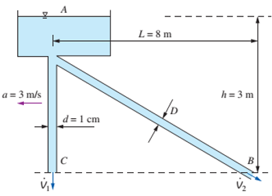
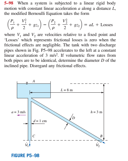
When a system is subjected to a linear rigid body motion with constant linear acceleration a along a distance L, the modified Bernoulli Equation takes the form ( P 1 ρ + V 1 2 2 + g z 1 ) − ( P 2 ρ + V 2 2 2 + g z ) = a L + Losses where V 1 and V 2 , are velocities relative to a fixed point and Losses’ which represents frictional losses is zero when the frictional effects are negligible. The tank with two discharge pipes shown in Fig. P5−98 accelerates to the left at a constant linear acceleration of 3 m/s 2 . If volumetric flow rates from both pipes are to be identical, determine the diameter D of the inclined pipe. Disregard any frictional effects. FIGURE P5−98
When a system is subjected to a linear rigid body motion with constant linear acceleration a along a distance L, the modified Bernoulli Equation takes the form ( P 1 ρ + V 1 2 2 + g z 1 ) − ( P 2 ρ + V 2 2 2 + g z ) = a L + Losses where V 1 and V 2 , are velocities relative to a fixed point and Losses’ which represents frictional losses is zero when the frictional effects are negligible. The tank with two discharge pipes shown in Fig. P5−98 accelerates to the left at a constant linear acceleration of 3 m/s 2 . If volumetric flow rates from both pipes are to be identical, determine the diameter D of the inclined pipe. Disregard any frictional effects. FIGURE P5−98
Solution Summary: The author explains the diameter of the inclined pipe and the volumetric flow rates from both pipes.
When a system is subjected to a linear rigid body motion with constant linear acceleration a along a distance L, the modified Bernoulli Equation takes the form
(
P
1
ρ
+
V
1
2
2
+
g
z
1
)
−
(
P
2
ρ
+
V
2
2
2
+
g
z
)
=
a
L
+
Losses
where
V
1
and
V
2
, are velocities relative to a fixed point and Losses’ which represents frictional losses is zero when the frictional effects are negligible. The tank with two discharge pipes shown in Fig. P5−98 accelerates to the left at a constant linear acceleration of 3
m/s
2
. If volumetric flow rates from both pipes are to be identical, determine the diameter D of the inclined pipe. Disregard any frictional effects.
The beam AB is attached to the wall in the xz plane by a
fixed support at A. A force of
F = (−129î + 69.0ĵ + 3591) N is applied to the end of
the beam at B. The weight of the beam can be modeled with
a uniform distributed load of intensity w = 85.0 N/m acting in
the negative z direction along its entire length. Find the
support reactions at A.
Z
с
A
b
a
B
F
y
Cc 10
BY NC SA
2016 Eric Davishahl
X
Values for dimensions on the figure are given in the following.
table. Note the figure may not be to scale.
Variable
Value
a
5.60 m
b
5.00 m
C
3.70 m
A
II
=
MA = (
m
2.>
~.>
+
+
k) N
k) N-
need help?
A bent pipe is attached to a wall with brackets as shown. A
force of F = 180 lb is applied to the end of the tube with
direction indicated by the dimensions in the figure.
Determine the support reactions at the brackets B, C, and
D. Model these brackets as journal bearings (only force
reactions perpendicular to the axis of the tube) and neglect
couple moment reactions. Assume the distance between the
supports at B and C and the tube bends nearby are
negligible such that the support at C is directly above the
support at D and the dimension g gives the distance between
supports B and C. Enter your answers in Cartesian
components.
2013 Michael Swanbom
cc 10
BY NC SA
g
h
א
B
8°
У
A
C
x
каж
Values for dimensions on the figure are given in the table
below. Note the figure may not be to scale.
Variable Value
a
6.72 in
b
11.8 in
с
14.8 in
d
42.0 in
h
26.6 in
g
28.0 in
→
The reaction at B is B =
lb.
The reaction at C is C =
lb.
The reaction at D is D =
lb.
+
<<
+
+
2.
+
+
557
〈ん
Need a deep-dive on the concept behind this application? Look no further. Learn more about this topic, mechanical-engineering and related others by exploring similar questions and additional content below.


 Elements Of ElectromagneticsMechanical EngineeringISBN:9780190698614Author:Sadiku, Matthew N. O.Publisher:Oxford University Press
 Mechanics of Materials (10th Edition)Mechanical EngineeringISBN:9780134319650Author:Russell C. HibbelerPublisher:PEARSON
 Thermodynamics: An Engineering ApproachMechanical EngineeringISBN:9781259822674Author:Yunus A. Cengel Dr., Michael A. BolesPublisher:McGraw-Hill Education
 Control Systems EngineeringMechanical EngineeringISBN:9781118170519Author:Norman S. NisePublisher:WILEY
 Mechanics of Materials (MindTap Course List)Mechanical EngineeringISBN:9781337093347Author:Barry J. Goodno, James M. GerePublisher:Cengage Learning
 Engineering Mechanics: StaticsMechanical EngineeringISBN:9781118807330Author:James L. Meriam, L. G. Kraige, J. N. BoltonPublisher:WILEY