Fluid Mechanics Fundamentals And Applications
3rd Edition
ISBN: 9780073380322
Author: Yunus Cengel, John Cimbala
Publisher: MCGRAW-HILL HIGHER EDUCATION
expand_more
expand_more
format_list_bulleted
Concept explainers
Videos
Textbook Question
Chapter 5, Problem 26P
Consider a river flowing toward a lake at an average speed of 4 m/s at a rate of 500
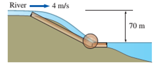
FIGURE P5−26
Expert Solution & Answer
Want to see the full answer?
Check out a sample textbook solution
Students have asked these similar questions
Qu 1 If crank OA rotates with an angular velocity of ω = 12 rad/s, determine the velocity of piston B and
the angular velocity of rod AB at the instant shown.
please show all work
Q2/ Maria has an online shop where she sells hand made paintings and
cards. She sells the painting for 50 and the card for 20. It takes her 2 hours
to complete 1 painting and 45 minutes to make a single card. She also has
a day job and makes paintings and cards in her free time. She cannot spend
more than 15 hours a week to make paintings and cards. Additionally, she
should make not more than 10 paintings and cards per week.
She makes a profit of 25 on painting and 15 on each card. How many
paintings and cards should she make each week to maximize her profit.
For the beam and loading shown, (a) draw the shear and bending moment diagrams, (b) determine the magnitude and location of the maximum absolute value of the bending momentConsider A = 0please show step by step process, i did something wrong with bending moment diagram( length of beam = 2 + 6 + 2)
Chapter 5 Solutions
Fluid Mechanics Fundamentals And Applications
Ch. 5 - Name four physical quantities that are conserved...Ch. 5 - Define mass and volume flow rates. How are they...Ch. 5 - Does the amount of mass entering a control volume...Ch. 5 - When is the flow through a control volume steady?Ch. 5 - Consider a device with one inlet and one outlet....Ch. 5 - In climates with low night-time temperatures, an...Ch. 5 - A garden hose attached with a nozzle is used to...Ch. 5 - Air whose density is 0.082 Ibm/ft3 enters the duct...Ch. 5 - A 0.7$-m3 rigid tank initially contains air whose...Ch. 5 - Consider the flow of an incompressible Newtonian...
Ch. 5 - Consider a fully filled tank of semi-circular...Ch. 5 - Prob. 12PCh. 5 - Prob. 13PCh. 5 - The minimum fresh air requirement of a residential...Ch. 5 - Air enters a nozzle steadily at 2.21 kg/m3 and 20...Ch. 5 - Air at 40°C flow steadily through the pipe shown...Ch. 5 - A hair dryer is basically a duct of constant...Ch. 5 - Define turbine efficiency, generator efficiency,...Ch. 5 - What is mechanical efficiency? What does a...Ch. 5 - How is the combined pump-motor efficiency of a...Ch. 5 - What is mechanical energy? How does it differ from...Ch. 5 - Prob. 22PCh. 5 - A differential thermocouple with sensors at the...Ch. 5 - Electric power is to be generated by installing a...Ch. 5 - Consider a river flowing toward a lake at an...Ch. 5 - Water is pumped from a lake to a storage tank 18 m...Ch. 5 - Prob. 28CPCh. 5 - Express the Bernoulli equation in three different...Ch. 5 - What are the three major assumptions used in the...Ch. 5 - Define static, dynamic, and hydrostatic pressure....Ch. 5 - What is streamwise acceleration? How does it...Ch. 5 - What is stagnation pressure? Explain how it can be...Ch. 5 - Prob. 34CPCh. 5 - How is the location of the hydraulic grade line...Ch. 5 - Prob. 36CPCh. 5 - What is the hydraulic grade line? How does it...Ch. 5 - A glass manometer with oil as the working fluid is...Ch. 5 - The velocity of a fluid flowing in a pipe is to be...Ch. 5 - The water level of a tank on a building roof is 20...Ch. 5 - Prob. 41CPCh. 5 - In a hydroelectric power plant, water enters the...Ch. 5 - A Pitot-static probe is used to measure the speed...Ch. 5 - The air velocity in the duct of a heating system...Ch. 5 - Prob. 45EPCh. 5 - A piezometer and a Pitot tube are tapped into a...Ch. 5 - The diameter of a cylindrical water tank is D0and...Ch. 5 - A siphon pumps water from a large reservoir to a...Ch. 5 - Prob. 49PCh. 5 - Water flows through a horizontal pipe at a rate of...Ch. 5 - An airplane is flying at an altitude of 10.500 m....Ch. 5 - While traveling on a dirt road, the bottom of a...Ch. 5 - The water in an 8-rn-diameter, 3-rn-high...Ch. 5 - Reconsider Prob. 5-49. Determine how long it will...Ch. 5 - Air at 105 kPa and 37°C flows upward through a...Ch. 5 - A handheld bicycle pump can be used as an atomizer...Ch. 5 - Water at 20°C is siphoned from a reservoir as...Ch. 5 - The water pressure in the mains of a city at a...Ch. 5 - A pressurized tank of water has a 10-cm-diameter...Ch. 5 - Air is flowing through a venturi meter whose...Ch. 5 - The water level in a tank is 15 m above the...Ch. 5 - A Pilot-static probe connected to a water...Ch. 5 - The air velocity in a duct is measured by a...Ch. 5 - In cold climates, water pipes may freeze and burst...Ch. 5 - A well-fitting piston with 4 small holes in a...Ch. 5 - A fluid of density and viscosity flows through a...Ch. 5 - What is useful pump head? How is it related to the...Ch. 5 - Consider the steady adiabatic flow of an...Ch. 5 - What is irreversible head loss? How is it related...Ch. 5 - Consider the steady adiabatic flow of an...Ch. 5 - What is the kinetic energy correction factor? Is...Ch. 5 - The water level in a tank is 20 m above the...Ch. 5 - A person is filling a knee-high bucket with water...Ch. 5 - A 3-rn-high tank filled with water has a discharge...Ch. 5 - In a hydroelectric power plant, water flows from...Ch. 5 - Reconsider Prob. 5-78E. Determine the flow rate of...Ch. 5 - An oil pump is drawing 25 kW of electric power...Ch. 5 - Tater is being pumped from a large lake to a...Ch. 5 - A 15-hp (shaft) pump is used to raise water to a...Ch. 5 - Water flows at a rate of 0.035 m3/s in a...Ch. 5 - The water level in a tank is 20 m above the...Ch. 5 - A hydraulic turbine has 50 m of head available at...Ch. 5 - A fan is to be selected to ventilate a bathroom...Ch. 5 - Water flows at a rate of 20 L/s through a...Ch. 5 - The water level in a tank is 34 ft above the...Ch. 5 - A large tank is initially filled with water 5 m...Ch. 5 - Water enters a hydraulic turbine through a...Ch. 5 - The velocity profile for turbulent flow in a...Ch. 5 - Water is pumped from a lower reservoir to a higher...Ch. 5 - Water in a partially filled large tank is to be...Ch. 5 - Underground water is to be pumped by a 78 percent...Ch. 5 - Reconsider Prob. 5-88. Determine the flow rate of...Ch. 5 - A 78-percent efficient 12-hp pump is pumping water...Ch. 5 - The demand for electric power is usually much...Ch. 5 - When a system is subjected to a linear rigid body...Ch. 5 - A fireboat is to fight fires at coastal areas by...Ch. 5 - The velocity of a liquid flowing in a circular...Ch. 5 - Air at 250 kgrn3 enters a nozzle that has an...Ch. 5 - The water level in a tank is 70 ft above the...Ch. 5 - A pressurized 2-rn-diameter tank of water has a...Ch. 5 - Air flows through a pipe at a rate of 120 L/s. The...Ch. 5 - A very large tank contains air at 102 kPa at a...Ch. 5 - Water is flowing through a Venturi meter whose...Ch. 5 - Water flows at a rate of 0.011 m3/s in a...Ch. 5 - The air in a 6-m × 5-m × 4-m hospital room is to...Ch. 5 - Underground water is being pumped into a pool...Ch. 5 - A 3-rn-high large tank is initially filled with...Ch. 5 - Reconsider Prob. 5-105. In order to dram the tank...Ch. 5 - A D0=8 -m-diameter tank is initially filled with...Ch. 5 - In some applications, elbow-type flow meters like...Ch. 5 - The cylindrical water tank with a valve at the...Ch. 5 - A rigid tank of volume 1.5 m3 initially contains...Ch. 5 - A wind tunnel draws atmospheric air at 20°C and...Ch. 5 - Water flows in a 5-cm-diameter pipe at a velocity...Ch. 5 - Air at 100 kPa and 20°C flows in a 12-cm-diameter...Ch. 5 - A water tank initially contains 140 L of water....Ch. 5 - Water enters a 4-cm-diameter pipe at a velocity of...Ch. 5 - The pressure of water is increased from 100 kPa to...Ch. 5 - A 75-m-high water body that is open to the...Ch. 5 - A pump is used to increase the pressure of water...Ch. 5 - A hydraulic turbine is used to generate power by...Ch. 5 - The motor of a pump consumes 1.05 hp of...Ch. 5 - The efficiency of a hydraulic turbine-generator...Ch. 5 - Which parameter is not related in the Bernoulli...Ch. 5 - Consider incompressible, frictionless flow of a...Ch. 5 - Consider incompressible, frictionless flow of...Ch. 5 - Consider water flow in a piping network. The...Ch. 5 - The static and stagnation pressures of a fluid in...Ch. 5 - The static and stagnation pressures of a fluid in...Ch. 5 - The difference between the heights of energy grade...Ch. 5 - Water at 120 kPa (gage) is flowing in a horizontal...Ch. 5 - Water is withdrawn a the bottom of a large tank...Ch. 5 - Water at 80 kPa (gage) enters a horizontal pipe at...Ch. 5 - Seawater is to be pumped into a large tank at a...Ch. 5 - Water enters a pump at 350 kPa at a rate of 1...Ch. 5 - An adiabatic pump is used to increase the pressure...Ch. 5 - The shaft power from a 90 percent-efficient...Ch. 5 - Using a 1are bucket whose volume is known and...Ch. 5 - Your company is setting up an experiment that...Ch. 5 - Computer-aided designs, the use of better...Ch. 5 - Using a handheld bicycle pump to generate an air...Ch. 5 - Using a flexible drinking straw and a ruler,...Ch. 5 - The power generated by a wind turbine is...
Knowledge Booster


Learn more about
Need a deep-dive on the concept behind this application? Look no further. Learn more about this topic, mechanical-engineering and related others by exploring similar questions and additional content below.Similar questions
- CORRECT ANSWER ONLY WITH COMPLETE FBD. PREFERABLY HANDWRITTEN. I WILL UPVOTE 1. The beam shown carries the following loads:Total dead load, wDL = 36 kN/mConcentrated live load, PLL = 240 kNThe beam section is HSS16X12X3/8 with properties:Span, L = 6 mArea, A = 12,100 mm2Moment of inertia about x-axis, Ix = 292 x 106 mm4Fy = 345 MPa 1. Calculate the location of the live load, from the left support, for maximum moment to occur at the fixed support.Answer: 2.536 m2. Calculate the maximum moment. Answer: 439.128 kN-marrow_forwardCORRECT ANSWER AND COMPLETE FBD ONLY. I PREFER HANDWRITTEN BUT ITS OKAY IF NOT. I WILL UPVOTE 2. The space truss shown is supported by ball-and-socket joints at A, B and C. Factored loads P1 and P2 areacting on joints D and E, respectively, towards the negative y-direction. 1. Calculate the stress of member CE, indicate tension or compression. Answer: 23.61 MPa Tension2. Calculate the stress of member AD, indicate tension or compression. Answer: 21.01 MPa Compression3. Calculate the stress of member CD, indicate tension or compression. Answer: 11.03 MPa Tensionarrow_forwardCORRECT ANSWER AND COMPLETE FBD ONLY. I PREFER HANDWRITTEN BUT ITS OKAY IF NOT. I WILL UPVOTE 3. The frame has pin supports at A and E, subject to a wind load. Treat joint C to be an internal hinge. Given:Dimensions, H1 = 3.0 m; H2 = 4.5 m; L = 10.0 mWind loads, wWL (AB) = 4.8 kN/m; wWL (BC) = 3.9 kN/m; wWL (CD) = 1.5 kN/m; wWL (DE) = 1.2 kN/mMembers are made of A36 steel Wide Flange Section with the following properties:Area, A = 64000 mm2Depth, d = 762 mmFlange width, bf = 371 mmThickness of web, tw = 32 mmThickness of flange, tf = 57.9 mmMoment of inertia about x-axis, Ix = 6080 x 106 mm4The wide flange is oriented so that the bending is about the x-axis1. Calculate the stress in member AB, due to the axial load it carries, indicate if tension or compression.Answer: 0.0476 MPa Tension2. Calculate the stress in member DE, due to the axial load it carries, indicate if tension or compression.Answer: 0.2351 MPa Compression3. Calculate the maximum bending stress at B. Answer: 4.282 MPaarrow_forward
- 32 mm 32 mm b' c' C 32 mm 32 mm b PROBLEM 6.41 a The extruded beam shown has a uniform wall thickness of 3 mm. Knowing that the vertical shear in the beam is 9 kN, determine the shearing stress at each of the five points indicated.arrow_forwardIn a structural reliability problem, the resistance (capacity) R and load effect (demand) S random variables associated with a failure mode of the structure of interest are normally distributed and statistically independent with the following probability distribution parameters (or statistics) in consistent units: MR = 12, σR = 3 μs = 5, σs = 2 (a) Determine the exact probability of failure pF ·arrow_forwardThe resistance R and load effect S for a given failure mode are statistically independent random variables with marginal PDF's 1 fR (r) = 0≤r≤100 100' fs(s)=0.05e-0.05s (a) Determine the probability of failure by computing the probability content of the failure domain defined as {rarrow_forwardPlease solve this problem as soon as possible My ID# 016948724arrow_forwardThe gears shown in the figure have a diametral pitch of 2 teeth per inch and a 20° pressure angle. The pinion rotates at 1800 rev/min clockwise and transmits 200 hp through the idler pair to gear 5 on shaft c. What forces do gears 3 and 4 transmit to the idler shaft? TS I y 18T 32T This a 12 x 18T C 48T 5arrow_forwardQuestion 1. Draw 3 teeth for the following pinion and gear respectively. The teeth should be drawn near the pressure line so that the teeth from the pinion should mesh those of the gear. Drawing scale (1:1). Either a precise hand drawing or CAD drawing is acceptable. Draw all the trajectories of the involute lines and the circles. Specification: 18tooth pinion and 30tooth gear. Diameter pitch=P=6 teeth /inch. Pressure angle:20°, 1/P for addendum (a) and 1.25/P for dedendum (b). For fillet, c=b-a.arrow_forward5. The figure shows a gear train. There is no friction at the bearings except for the gear tooth forces. The material of the milled gears is steel having a Brinell hardness of 170. The input shaft speed (n2) is 800 rpm. The face width and the contact angle for all gears are 1 in and 20° respectively. In this gear set, the endurance limit (Se) is 15 kpsi and nd (design factor) is 2. (a) Find the revolution speed of gear 5. (b) Determine whether each gear satisfies the design factor of 2.0 for bending fatigue. (c) Determine whether each gear satisfies the design factor of 2.0 for surface fatigue (contact stress). (d) According to the computation results of the questions (b) and (c), explain the possible failure mechanisms for each gear. N4=28 800rpm N₁=43 N5=34 N₂=14 P(diameteral pitch)=8 for all gears Coupled to 2.5hp motorarrow_forward1. The rotating steel shaft is simply supported by bearings at points of B and C, and is driven by a spur gear at D, which has a 6-in pitch diameter. The force F from the drive gear acts at a pressure angle of 20°. The shaft transmits a torque to point A of TA =3000 lbĘ in. The shaft is machined from steel with Sy=60kpsi and Sut=80 kpsi. (1) Draw a shear force diagram and a bending moment diagram by F. According to your analysis, where is the point of interest to evaluate the safety factor among A, B, C, and D? Describe the reason. (Hint: To find F, the torque Tд is generated by the tangential force of F (i.e. Ftangential-Fcos20°) When n=2.5, K=1.8, and K₁ =1.3, determine the diameter of the shaft based on (2) static analysis using DE theory (note that fatigue stress concentration factors need to be used for this question because the loading condition is fatigue) and (3) a fatigue analysis using modified Goodman. Note) A standard diameter is not required for the questions. 10 in Darrow_forward3 N2=28 P(diametral pitch)=8 for all gears Coupled to 25 hp motor N3=34 Full depth spur gears with pressure angle=20° N₂=2000 rpm (1) Compute the circular pitch, the center-to-center distance, and base circle radii. (2) Draw the free body diagram of gear 3 and show all the forces and the torque. (3) In mounting gears, the center-to-center distance was reduced by 0.1 inch. Calculate the new values of center-to-center distance, pressure angle, base circle radii, and pitch circle diameters. (4)What is the new tangential and radial forces for gear 3? (5) Under the new center to center distance, is the contact ratio (mc) increasing or decreasing?arrow_forwardarrow_back_iosSEE MORE QUESTIONSarrow_forward_ios
Recommended textbooks for you
 Refrigeration and Air Conditioning Technology (Mi...Mechanical EngineeringISBN:9781305578296Author:John Tomczyk, Eugene Silberstein, Bill Whitman, Bill JohnsonPublisher:Cengage Learning
 Principles of Heat Transfer (Activate Learning wi...Mechanical EngineeringISBN:9781305387102Author:Kreith, Frank; Manglik, Raj M.Publisher:Cengage Learning
 International Edition---engineering Mechanics: St...Mechanical EngineeringISBN:9781305501607Author:Andrew Pytel And Jaan KiusalaasPublisher:CENGAGE L
Refrigeration and Air Conditioning Technology (Mi...
Mechanical Engineering
ISBN:9781305578296
Author:John Tomczyk, Eugene Silberstein, Bill Whitman, Bill Johnson
Publisher:Cengage Learning
Principles of Heat Transfer (Activate Learning wi...
Mechanical Engineering
ISBN:9781305387102
Author:Kreith, Frank; Manglik, Raj M.
Publisher:Cengage Learning
International Edition---engineering Mechanics: St...
Mechanical Engineering
ISBN:9781305501607
Author:Andrew Pytel And Jaan Kiusalaas
Publisher:CENGAGE L
Fluid Mechanics - Viscosity and Shear Strain Rate in 9 Minutes!; Author: Less Boring Lectures;https://www.youtube.com/watch?v=_0aaRDAdPTY;License: Standard youtube license