
Videos
For the circuit shown in Figure P5.52, let
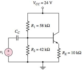
Figure P5.52
a.
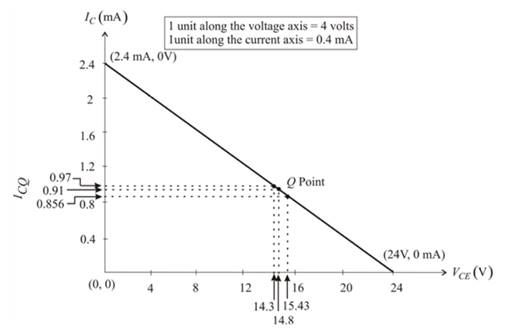
The ICQ and VCEQ and then sketching the load line and plotting the Q-point.
Answer to Problem 5.52P
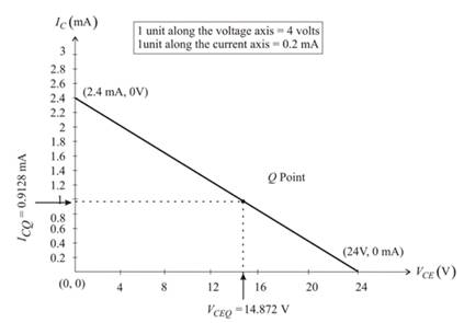
The ICQ and VCEQ :
ICQ =0.9128mA.
VCEQ =14.87V.
Explanation of Solution
Given:
The value of the attenuation factor,
The circuit diagram is shown below:

The Thevenin resistance is evaluated as:
Applying the voltage division rule to evaluate the Thevenin voltage:
Redrawing the given circuit:
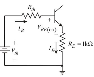
Applying the Kirchhoff’s voltage law in the base-emitter loop:
By the expression of the common emitter current gain:
The quiescent collector emitter voltage is given as:
Hence, the load line equation is given as:
The coordinates of the end points of the load line.
Since, VCE =0-V.
Hence,
Now, substituting IC =0A, then:
Hence, the coordinates of the two extremities of the load line is:
Sketching the load line graph:
b.
The range of the ICQ and VCEQ and plotting the various Q-point on the load line.
Explanation of Solution
Given:
The value of the attenuation factor,
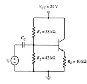
The circuit diagram is shown below:
The resistor R1 and R2 vary by the
Now, evaluating the range of the resistor:
Now, evaluating the range of the R2:
Now taking
as R1 and R2 respectively:
Evaluating the Thevenin resistance using the equation 1:
Applying the voltage division rule to evaluate the Thevenin voltage using the equation 2:
By the use of the equation 3:
Now, from the equation 4:
Now taking
as R1 and R2 respectively:
Evaluating the Thevenin resistance using the equation 1:
Applying the voltage division rule to evaluate the Thevenin voltage using the equation 2:
By the use of the equation 3:
Now, from the equation 4:
Now taking
as R1 and R2 respectively:
Evaluating the Thevenin resistance using the equation 1:
Applying the voltage division rule to evaluate the Thevenin voltage using the equation 2:
By the use of the equation 3:
Now, from the equation 4:
Hence, the plot for the various Q points on the load line is:
Want to see more full solutions like this?
Chapter 5 Solutions
Microelectronics: Circuit Analysis and Design


- use this code on the bottom to answer the question in the photo clc; clearvars; % Read the file [y, Fs] = audioread('106miles.wav'); N = length(y); Nfft = 2^nextpow2(N); dt = 1/Fs; t = (0:dt:(N-1)*dt)'; % Ensure t is a column vector y = y - mean(y); % Remove DC component (if not already zero-mean) % Carrier signal (25 kHz) fc = 25000; % Carrier frequency in Hz carrier = cos(2 * pi * fc * t); % DSB-SC Modulation modulated_signal = y .* carrier; % Plot Time Domain Signal figure; subplot(2,1,1); plot(t, y); title('Original Signal (Time Domain)'); xlabel('Time (s)'); ylabel('Amplitude'); subplot(2,1,2); plot(t, modulated_signal); title('DSB-SC Modulated Signal (Time Domain)'); xlabel('Time (s)'); ylabel('Amplitude'); % Frequency Domain (FFT) Y = fft(y, Nfft) / Nfft; Modulated_Y = fft(modulated_signal, Nfft) / Nfft; f = Fs * (0:(Nfft/2)) / Nfft; % Frequency vector % Plot Frequency Domain Signal figure; subplot(2,1,1); plot(f, abs(Y(1:Nfft/2+1))); title('Original Signal…arrow_forward5-9 A 230 V shunt motor has a nominal arma- ture current of 60 A. If the armature resist- ance is 0.152, calculate the following: a. The counter-emf [V] b. The power supplied to the armature [W] c. The mechanical power developed by the motor, [kW] and [hp] 5-10 a. In Problem 5-9 calculate the initial start- ing current if the motor is directly con- nected across the 230 V line. b. Calculate the value of the starting resistor needed to limit the initial current to 115 A.arrow_forwardhow to solve this?arrow_forward
- For the circuit in Fig. P8.52, choose the load impedance ZLso that the power dissipated in it is a maximum. How much powerwill that be?arrow_forwardhow to solve the attached question? please explain or give reference where required in the solution.arrow_forwardHANDWRITTEN SOLUTION REQUIRED NOT USING CHATGPTarrow_forward
- Please only do part E and F. Please show your work and be as detailed as possible. Please explain the relationship between K the gain and stability of the system. Also, show how to plot the poles and why they are on either the real or imaginary axis. What is it about the example that indicated that? thank youarrow_forwardPlease draw the block diagram for this problem and explain how. thank youarrow_forwardPlease show your work and be as detailed as possible. I would like to really understand the connection between the type of loop, the dampness, and the gain, K. Thank youarrow_forward
- In the zone refining of silicon, an RF-heater is used to remove trace amounts of impuritiesfrom the silicon. If the silicon has the impurity of 10^14 Co (k = 8*10^-6) what is the purityof the crystal after one pass of the zone refiner? After two passes? Plot concentration as afunction of crystal length from 0 to 8ft (total length of the crystal). The width of the moltenzone is 5”.arrow_forwardNot use ai pleasearrow_forwardSolve on paper not using AI or chatgptarrow_forward
 Introductory Circuit Analysis (13th Edition)Electrical EngineeringISBN:9780133923605Author:Robert L. BoylestadPublisher:PEARSON
 Delmar's Standard Textbook Of ElectricityElectrical EngineeringISBN:9781337900348Author:Stephen L. HermanPublisher:Cengage Learning
 Programmable Logic ControllersElectrical EngineeringISBN:9780073373843Author:Frank D. PetruzellaPublisher:McGraw-Hill Education
 Fundamentals of Electric CircuitsElectrical EngineeringISBN:9780078028229Author:Charles K Alexander, Matthew SadikuPublisher:McGraw-Hill Education
 Electric Circuits. (11th Edition)Electrical EngineeringISBN:9780134746968Author:James W. Nilsson, Susan RiedelPublisher:PEARSON
 Engineering ElectromagneticsElectrical EngineeringISBN:9780078028151Author:Hayt, William H. (william Hart), Jr, BUCK, John A.Publisher:Mcgraw-hill Education,