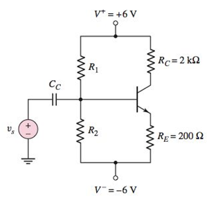
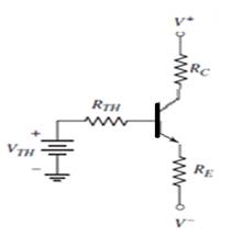
For the circuit shown in Figure P5.61, the bias voltages are changed to V + = 3V and V − = − 3V . (a) Design a bias−stable circuit for β = 120 such that V C E Q = 2.8 V . Determine I C Q , R 1 , and R 2 . (b) If the resistors R 1 and R 2 vary by ±5 percent, determine the range in I C Q and V C E Q . Plot the various Q −points on the load line. Figure P5.61
For the circuit shown in Figure P5.61, the bias voltages are changed to V + = 3V and V − = − 3V . (a) Design a bias−stable circuit for β = 120 such that V C E Q = 2.8 V . Determine I C Q , R 1 , and R 2 . (b) If the resistors R 1 and R 2 vary by ±5 percent, determine the range in I C Q and V C E Q . Plot the various Q −points on the load line. Figure P5.61
For the circuit shown in Figure P5.61, the bias voltages are changed to
V
+
=
3V
and
V
−
=
−
3V
. (a) Design a bias−stable circuit for
β
=
120
such that
V
C
E
Q
=
2.8
V
. Determine
I
C
Q
,
R
1
, and
R
2
. (b) If the resistors
R
1
and
R
2
vary by ±5 percent, determine the range in
I
C
Q
and
V
C
E
Q
. Plot the various Q−points on the load line.
Figure P5.61
a.
Expert Solution
To determine
The design parameters of the circuit and the collector current at Q -point.
Answer to Problem D5.62P
ICQ=1.453 mA , R1=14.21 kΩ and R2=2.92 kΩ .
Explanation of Solution
Given Information:
β=120,VCEQ=2.8 V, V+=3 V and V−=−3 V
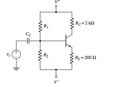
The given circuit is shown below.
Calculation:
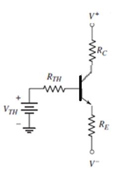
First, redraw the circuit with a Thevenin equivalent circuit in the base. Then find the Thevenin equivalent voltage and resistance. Calculate the transistor currents and voltages. Then find the required resistor values using the equations for Thevenin voltage and Thevenin resistance. The below figure shows the circuit with the Thevenin equivalent circuit at the base of the transistor.
Calculation:
Applying Kirchhoff’s law around C-E loop
V+=VCEQ+IEQRE+ICQRC+V−V+=VCEQ+((1+ββ)RE+RC)ICQ+V−ICQ=V+−VCEQ−V−(1+ββ)RE+RC=3−2.8−(−3)(1+120120)0.2+2 mA
ICQ=1.453 mA
Thevenin equivalent resistance is
RTH=0.1(1+β)RE=0.1×121×0.2 kΩ= 2.42 kΩ
Applying Kirchhoff’s voltage law around the B-E loop,
VTH=VBE(on)+IEQRE+IBQRTH+V−VTH=VBE(on)+(1+ββ)ICQRE+(1β)ICQRTH+V−VTH=V−+VBE(on)+(1+ββ)ICQRE+(1β)IcQRTHVTH=−3+0.7+(1+120120)×1.453×0.2+(1120)×1.453×2.42VTH=−1.978 V
Thevenin resistance is,
RTH=(R1R2R1+R2)(R1R2R1+R2)=2.42→(1)
Thevenin voltage is,
VTH=(R2R1+R2)(V+−V−)+V−
Using equation (1), rewrite the above equation as,
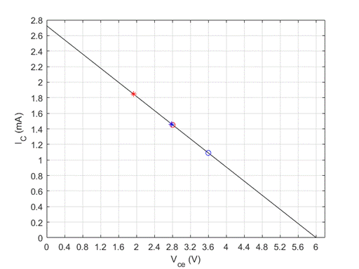
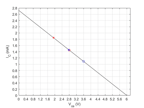
The range of Q -point values, ICQ and VCEQ for the percent change of bias resistors.
To plot: Various Q -pints on the load line.
Answer to Problem D5.62P
The range of values is
1.0906 mA≤ICQ≤1.8452 mA and 1.9375 V≤VCEQ≤3.599 V
Th plot is shown below.
Explanation of Solution
Given Information:
β=120,V+=3 V and V−=−3 VChange of bias resistence is ±5%
The given transistor circuit is shown below.
Calculaion:
First, redraw the circuit with a Thevenin equivalent circuit in the base. Then find the Thevenin equivalent voltage and resistance. Calculate the transistor currents and voltages at Q -point.
Thevenin resistance is,
RTH=(R1R2R1+R2)→(1)
Thevenin voltage is,
VTH=(R2R1+R2)(V+−V−)+V−→(2)
Applying Kirchhoff’s voltage law around the B-E loop,
Add a second start button to the basic circuit so Start Button 1 or Start Button 2 can be used to start a motor. Include a second stop button that is connected so that Stop Button 1 or Start Button 2 can be used to stop the motor.
Circuit Logic. Match each statement to the proper circuit. All circuits have been drawn with a light (L) to represent the load, whether it is a motor, bell, or any other kind of load. In addition, each switch is illustrated as a pushbutton whether it is a maintained switch, momentary switch, pushbutton, switch-on target, or any other type of switch.
from electrical motor controls for integrated systems workbook 2014 chapter 5
Need a deep-dive on the concept behind this application? Look no further. Learn more about this topic, electrical-engineering and related others by exploring similar questions and additional content below.


 Introductory Circuit Analysis (13th Edition)Electrical EngineeringISBN:9780133923605Author:Robert L. BoylestadPublisher:PEARSON
 Delmar's Standard Textbook Of ElectricityElectrical EngineeringISBN:9781337900348Author:Stephen L. HermanPublisher:Cengage Learning
 Programmable Logic ControllersElectrical EngineeringISBN:9780073373843Author:Frank D. PetruzellaPublisher:McGraw-Hill Education
 Fundamentals of Electric CircuitsElectrical EngineeringISBN:9780078028229Author:Charles K Alexander, Matthew SadikuPublisher:McGraw-Hill Education
 Electric Circuits. (11th Edition)Electrical EngineeringISBN:9780134746968Author:James W. Nilsson, Susan RiedelPublisher:PEARSON
 Engineering ElectromagneticsElectrical EngineeringISBN:9780078028151Author:Hayt, William H. (william Hart), Jr, BUCK, John A.Publisher:Mcgraw-hill Education,