
Applied Statics and Strength of Materials (6th Edition)
6th Edition
ISBN: 9780133840544
Author: George F. Limbrunner, Craig D'Allaird, Leonard Spiegel
Publisher: PEARSON
expand_more
expand_more
format_list_bulleted
Concept explainers
Videos
Textbook Question
Chapter 5, Problem 5.32SP
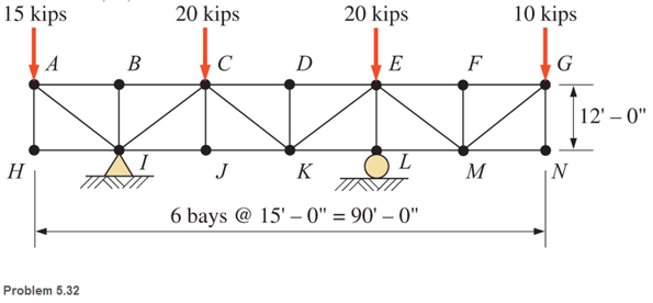
For Problems 5.32  through 5.38,
  calculate the forces in the indicated members of the trusses shown. Use the method of sections.
5.32 Member CD, CK, and EM.
Expert Solution & Answer
Want to see the full answer?
Check out a sample textbook solution
Students have asked these similar questions
Example find f(t)?
-4s
F(s)=
(s² + 4)²
draw a kinematic diagram
Rigid bodies ENG2016. Full complete solutions need okk don't use guidelines but solve full accurate steps by steps don't use chat gpt or any other ai okkk just solve complete solutions okkk take your time but solve complete solutions
Chapter 5 Solutions
Applied Statics and Strength of Materials (6th Edition)
Ch. 5 - through 5.7 Calculate the forces in all members of...Ch. 5 - Calculate the forces in all members of the trusses...Ch. 5 - Calculate the forces in all members of the trusses...Ch. 5 - Calculate the forces in all members of the trusses...Ch. 5 - Calculate the forces in all members of the trusses...Ch. 5 - Calculate the forces in all members of the trusses...Ch. 5 - Calculate the forces in all members of the trusses...Ch. 5 - Determine the forces in members CD, DH, and HI for...Ch. 5 - Determine the forces in members BC, BE, and FE for...Ch. 5 - Determine the forces in members BC, CH, and CG in...
Ch. 5 - For the Howe roof truss shown, determine the...Ch. 5 - Determine the forces in members DE, CE, and BC in...Ch. 5 - Calculate the forces in members BC, BG, and FG for...Ch. 5 - Determine the forces in members CD, BD, BE, and CB...Ch. 5 - A pin-connected A-frame supports a load, as shown....Ch. 5 - Determine the pin reactions at pins A, B, and C in...Ch. 5 - Calculate the pin reactions at each of the pins in...Ch. 5 - A bracket is pin connected at points A, B, and D...Ch. 5 - A pin-connected frame is loaded, as shown....Ch. 5 - The cylinder shown has a mass of 500 kg. Determine...Ch. 5 - A simple frame is pin connected at points A, B,...Ch. 5 - Using the method of sections, determine the forces...Ch. 5 - Using the method of sections, determine the forces...Ch. 5 - through 5.31 Calculate the forces in all members...Ch. 5 - Calculate the forces in all members of the trusses...Ch. 5 - Calculate the forces in all members of the trusses...Ch. 5 - Calculate the forces in all members of the trusses...Ch. 5 - Calculate the forces in all members of the trusses...Ch. 5 - Calculate the forces in all members of the trusses...Ch. 5 - Calculate the forces in all members of the trusses...Ch. 5 - Calculate the forces in all members of the trusses...Ch. 5 - For Problems 5.32 through 5.38, calculate the...Ch. 5 - For Problem 5.32 through 5.38, Calculate the...Ch. 5 - For Problems 5.32 through 5.38, calculate the...Ch. 5 - For Problems 5.32 through 5.38, calculate the...Ch. 5 - For Problem 5.32 through 5.38 , Calculate the...Ch. 5 - For Problems 5.32 through 5.38, calculate the...Ch. 5 - For Problems 5.32 through 5.38, calculate the...Ch. 5 - A pin-connected crane framework is loaded and...Ch. 5 - Calculate the pin reactions at pins A, B, and D in...Ch. 5 - Determine the pin reactions at pins A, B, and C in...Ch. 5 - The wall bracket shown is pin-connected at points...Ch. 5 - Calculate the pin reactions at each of the pins in...Ch. 5 - The A-frame shown is pin-connected at A,B,C, and...Ch. 5 - The tongs shown are used to grip an object. For an...Ch. 5 - A toggle joint is a mechanism by which a...Ch. 5 - In the toggle joint of Problem 5.46 , assume that...Ch. 5 -
Knowledge Booster


Learn more about
Need a deep-dive on the concept behind this application? Look no further. Learn more about this topic, mechanical-engineering and related others by exploring similar questions and additional content below.Similar questions
- Question 6 I need to show all work step by step dynamicsarrow_forwardQu. 3 The automobile is originally at rest s = 0. If it then starts to increase its speed at i = (0.05t2)ft/s?, where t is in seconds, determine the magnitudes of its velocity and acceleration at s = 550 ft. please show all work from dynamics step by step formulaarrow_forwardquestion 5 and 6 from dynamics I need to show all work step by step problemsarrow_forward
- Study Area Document Sharing User Settings Access Pearson mylabmastering.pearson.com P Pearson MyLab and Mastering The crash cushion for a highway barrier consists of a nest of barrels filled with an impact-absorbing material. The barrier stopping force is measured versus the vehicle penetration into the barrier. (Figure 1) Part A P Course Home b My Questions | bartleby Review Determine the distance a car having a weight of 4000 lb will penetrate the barrier if it is originally traveling at 55 ft/s when it strikes the first barrel. Express your answer to three significant figures and include the appropriate units. Figure 1 of 1 36 μΑ S = Value Units Submit Request Answer Provide Feedback ? Next >arrow_forwardWater is the working fluid in an ideal Rankine cycle. Saturated vapor enters the turbine at 12 MPa, and the condenser pressure is 8 kPa. The mass flow rate of steam entering the turbine is 50 kg/s. Determine: (a) the net power developed, in kW. (b) the rate of heat transfer to the steam passing through the boiler, in kW. (c) the percent thermal efficiency. (d) the mass flow rate of condenser cooling water, in kg/s, if the cooling water undergoes a temperature increase of 18°C with negligible pressure change in passing through the condenser.arrow_forward4. The figure below shows a bent pipe with the external loading FA 228 lb, and M₁ = M₂ = 1 kip-ft. The force Fernal loading FA = 300 lb, FB: parallel to the y-axis, and and yc = 60°. = 125 lb, Fc = acts parallel to the x-z plane, the force FB acts Cartesian resultan Coordinate direction angles of Fc are ac = 120°, ẞc = 45°, a. Compute the resultant force vector of the given external loading and express it in EST form. b. Compute the resultant moment vector of the given external loading about the origin, O, and express it in Cartesian vector form. Use the vector method while computing the moments of forces. c. Compute the resultant moment vector of the given external loading about the line OA and express it in Cartesian vector form. :00 PM EST k ghoufran@buffaternal du 2 ft M₁ A 40° FA M2 C 18 in 1 ft Fc 25 houfran@bald.edu - Feb 19, 3 ft FBarrow_forward
- The differential equation of a cruise control system is provided by the following equation: Find the closed loop transfer function with respect to the reference velocity (vr) . a. Find the poles of the closed loop transfer function for different values of K. How does the poles move as you change K? b. Find the step response for different values of K and plot in MATLAB. What can you observe? c. For the given transfer function, find tp, ts, tr, Mp . Plot the resulting step response. G(s) = 40/(s^2 + 4s + 40)arrow_forwardAuto Controls Perform the partial fraction expansion of the following transfer function and find the impulse response: G(s) = (s/2 + 5/3) / (s^2 + 4s + 6) G(s) =( 6s^2 + 50) / (s+3)(s^2 +4)arrow_forwardStudy Area Document Sharing User Settings mylabmastering.pearson.com Access Pearson P Pearson MyLab and Mastering The 150-lb skater passes point A with a speed of 6 ft/s. (Figure 1) Figure 1 of 1 Part A P Course Home b My Questions | bartleby Determine his speed when he reaches point B. Neglect friction. Express your answer to three significant figures and include the appropriate units. με ? VB = Value Units Submit Request Answer Part B Determine the normal force exerted on him by the track at this point. Express your answer to three significant figures and include the appropriate units. ☐ о Α NB = Value Units Submit Request Answer Provide Feedback ? ■Review Next >arrow_forward
- mylabmastering.pearson.com Access Pearson P Pearson MyLab and Mastering P Course Home b My Questions | bartleby Study Area Document Sharing User Settings The 100-kg crate is subjected to the forces shown. The crate is originally at rest. The coefficient of kinetic friction between the crate and the surface is μk = 0.2. (Figure 1) Part A Determine the distance it slides in order to attain a speed of 8.1 m/s. Express your answer to three significant figures and include the appropriate units. Figure 500 N 1 of 1 Α S = Value Units Submit Request Answer Provide Feedback ? ■Review Next >arrow_forwardThe differential equation of a DC motor can be described by the following equation Find the transfer function between the applied voltage ( Va)and the motor speed (thetadot m). What is the steady state speed of the motor after a voltage (Va = 10V) has been applied. Find the transfer function between the applied voltage (Va) and the shaft angle (thetadot m) .arrow_forwardStudy Area Document Sharing User Settings Access Pearson mylabmastering.pearson.com P Pearson MyLab and Mastering The crash cushion for a highway barrier consists of a nest of barrels filled with an impact-absorbing material. The barrier stopping force is measured versus the vehicle penetration into the barrier. (Figure 1) Part A P Course Home b My Questions | bartleby Review Determine the distance a car having a weight of 4000 lb will penetrate the barrier if it is originally traveling at 55 ft/s when it strikes the first barrel. Express your answer to three significant figures and include the appropriate units. Figure 1 of 1 36 μΑ S = Value Units Submit Request Answer Provide Feedback ? Next >arrow_forward
arrow_back_ios
SEE MORE QUESTIONS
arrow_forward_ios
Recommended textbooks for you
 International Edition---engineering Mechanics: St...Mechanical EngineeringISBN:9781305501607Author:Andrew Pytel And Jaan KiusalaasPublisher:CENGAGE L
International Edition---engineering Mechanics: St...
Mechanical Engineering
ISBN:9781305501607
Author:Andrew Pytel And Jaan Kiusalaas
Publisher:CENGAGE L
Engineering Basics - Statics & Forces in Equilibrium; Author: Solid Solutions - Professional Design Solutions;https://www.youtube.com/watch?v=dQBvQ2hJZFg;License: Standard YouTube License, CC-BY