
Applied Statics and Strength of Materials (6th Edition)
6th Edition
ISBN: 9780133840544
Author: George F. Limbrunner, Craig D'Allaird, Leonard Spiegel
Publisher: PEARSON
expand_more
expand_more
format_list_bulleted
Concept explainers
Videos
Textbook Question
Chapter 5, Problem 5.33SP
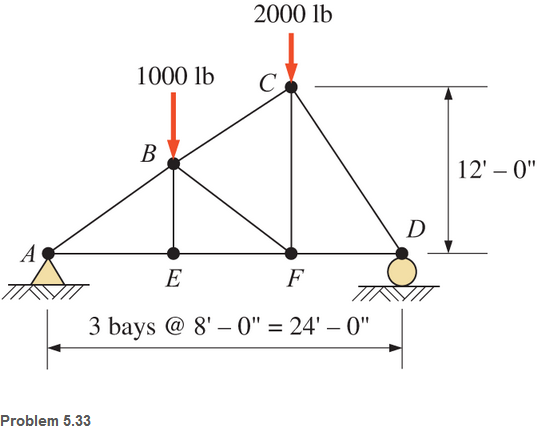
For Problem 5.32  through 5.38,
  Calculate the forces in the indicated members of the trusses shown. Use the method of sections.
5.33 Members BF, BC, and EF.
Expert Solution & Answer

Trending nowThis is a popular solution!

Students have asked these similar questions
An elastic bar of length L = 1m and cross section A = 1cm2 spins with
angular velocity ω about an axis, as shown in the figure below. The
radial acceleration at a generic point x along the bar is a(x) = ω2x,
where ω= 100rad/s is the angular velocity. The bar is pinned on the
rotation axis at x = 0. A mass M = 1kg is attached to the right end of
the bar. Due to the radial acceleration, the bar stretches along x with
displacement function u(x). The displacement u(x) solves the BVP
(strong form) sketched below:
d
dx (σ(x)) + ρa(x) = 0 PDE
σ(x) = E du
dx Hooke’s law
(1)
u(0) =?? essential BC
σ(L) =?? natural BC
where σ(x) is the axial stress in the rod, ρ= 2700kg /m3 is the mass
density, and E = 70GPa is the Young’s modulus
1. Define appropriate BCs for the strong BVP
2. Find the solution of the strong BVP analytically
3. Derive the weak form of the BVP.
Gruebler's formula for the following mechanism?
w/I
- |
العنوان
I need a detailed drawing with explanation
SOLL
эт
4
حكا
The guide vane angle of a reaction turbine (Francis type
make 20° with the tangent. The moving blade angle at entry is
120°. The external diameter of runner is 450 mm and the internal
diameter is 300 mm. Runner width at entry is 62.5mm and at exit
100mm. Calculate the blade angle at exit for radial discharge.
96252
-20125
750 ×2.01
Chapter 5 Solutions
Applied Statics and Strength of Materials (6th Edition)
Ch. 5 - through 5.7 Calculate the forces in all members of...Ch. 5 - Calculate the forces in all members of the trusses...Ch. 5 - Calculate the forces in all members of the trusses...Ch. 5 - Calculate the forces in all members of the trusses...Ch. 5 - Calculate the forces in all members of the trusses...Ch. 5 - Calculate the forces in all members of the trusses...Ch. 5 - Calculate the forces in all members of the trusses...Ch. 5 - Determine the forces in members CD, DH, and HI for...Ch. 5 - Determine the forces in members BC, BE, and FE for...Ch. 5 - Determine the forces in members BC, CH, and CG in...
Ch. 5 - For the Howe roof truss shown, determine the...Ch. 5 - Determine the forces in members DE, CE, and BC in...Ch. 5 - Calculate the forces in members BC, BG, and FG for...Ch. 5 - Determine the forces in members CD, BD, BE, and CB...Ch. 5 - A pin-connected A-frame supports a load, as shown....Ch. 5 - Determine the pin reactions at pins A, B, and C in...Ch. 5 - Calculate the pin reactions at each of the pins in...Ch. 5 - A bracket is pin connected at points A, B, and D...Ch. 5 - A pin-connected frame is loaded, as shown....Ch. 5 - The cylinder shown has a mass of 500 kg. Determine...Ch. 5 - A simple frame is pin connected at points A, B,...Ch. 5 - Using the method of sections, determine the forces...Ch. 5 - Using the method of sections, determine the forces...Ch. 5 - through 5.31 Calculate the forces in all members...Ch. 5 - Calculate the forces in all members of the trusses...Ch. 5 - Calculate the forces in all members of the trusses...Ch. 5 - Calculate the forces in all members of the trusses...Ch. 5 - Calculate the forces in all members of the trusses...Ch. 5 - Calculate the forces in all members of the trusses...Ch. 5 - Calculate the forces in all members of the trusses...Ch. 5 - Calculate the forces in all members of the trusses...Ch. 5 - For Problems 5.32 through 5.38, calculate the...Ch. 5 - For Problem 5.32 through 5.38, Calculate the...Ch. 5 - For Problems 5.32 through 5.38, calculate the...Ch. 5 - For Problems 5.32 through 5.38, calculate the...Ch. 5 - For Problem 5.32 through 5.38 , Calculate the...Ch. 5 - For Problems 5.32 through 5.38, calculate the...Ch. 5 - For Problems 5.32 through 5.38, calculate the...Ch. 5 - A pin-connected crane framework is loaded and...Ch. 5 - Calculate the pin reactions at pins A, B, and D in...Ch. 5 - Determine the pin reactions at pins A, B, and C in...Ch. 5 - The wall bracket shown is pin-connected at points...Ch. 5 - Calculate the pin reactions at each of the pins in...Ch. 5 - The A-frame shown is pin-connected at A,B,C, and...Ch. 5 - The tongs shown are used to grip an object. For an...Ch. 5 - A toggle joint is a mechanism by which a...Ch. 5 - In the toggle joint of Problem 5.46 , assume that...Ch. 5 -
Knowledge Booster


Learn more about
Need a deep-dive on the concept behind this application? Look no further. Learn more about this topic, mechanical-engineering and related others by exploring similar questions and additional content below.Similar questions
- Compressor Selection: (Q1) While a manufacturing cell is running, the calculated flow rate of air into a compressor is 40 SCFM. Which compressor from this list should be selected? A. A compressor that uses 80 SCFM B. A compressor that uses 40 SCFM C. A compressor that delivers 80 SCFM D. A compressor that delivers 40 SCFMarrow_forwardSCFM Calculation: (Q1) A pneumatic system running a manufacturing cell works on 80 psi and requires a flow rate of 10 CFM to operate. A compressor must be selected to run the cell. Calculate the amount of air going into the compressor to run this cell. (Hint: This will be in SCFM) Accurate to two decimals. Do not write the unit.arrow_forward: +00 العنوان >scóny : + 개 العنوان I need a actanicu urawing wit д い Ants nation Taxi pu +9635. The guide vane angle of a reaction turbine (Francis type make 20° with the tangent. The moving blade angle at entry is 120°. The external diameter of runner is 450 mm and the internal diameter is 300 mm. Runner width at entry is 62.5mm and at exit 100mm. Calculate the blade angle t exit for radial discharge. ۲/۱ = 44 985arrow_forward
- :+B العنوان I need a actanicu urawing with Car nation The guide vane angle of a reaction turbine (Francis type make 20° with the tangent. The moving blade angle at entry is 120° The external diameter of runner is 450 mm and the internal diameter is 300 mm. Runner width at entry is 62.5mm and at exit 100mm. Calculate the blade angle at exit for radial discharge.arrow_forwardGay-Lussac's Law: (Q2) A gas in a pressure vessel has a temperature of 40 °C and a pressure of 20 psi. Heat is added and its pressure rises to 80 psi. What is the new temperature in °C? Use Two decimal places. Do not write the unit.arrow_forward:+B العنوان I need a actanicu urawing with Car nation The guide vane angle of a reaction turbine (Francis type make 20° with the tangent. The moving blade angle at entry is 120° The external diameter of runner is 450 mm and the internal diameter is 300 mm. Runner width at entry is 62.5mm and at exit 100mm. Calculate the blade angle at exit for radial discharge.arrow_forward
- The volume of a gas is increased, and the temperature is maintained consent. The original volume was 1200 mm3 and its pressure was 100 psi. What is the new pressure in psi, if the volume is increased to 2250 mm3? Use Two decimal places. Do not write the unit.arrow_forward:+B العنوان I need a actanicu urawing with Car nation The guide vane angle of a reaction turbine (Francis type make 20° with the tangent. The moving blade angle at entry is 120° The external diameter of runner is 450 mm and the internal diameter is 300 mm. Runner width at entry is 62.5mm and at exit 100mm. Calculate the blade angle at exit for radial discharge.arrow_forwardThe guide vane angle of a reaction turbine (Francis type make 20° with the tangent. The moving blade angle at entry is 120°. The external diameter of runner is 450 mm and the internal diameter is 300 mm. Runner width at entry is 62.5mm and at exit 100mm. Calculate the blade angle at exit for radial discharge.arrow_forward
- answer this as soon as possible, please.arrow_forwardA piston–cylinder device contains 50 kg of water at 250 kPa and 25°C. The cross-sectional area of the piston is 0.1 m2. Heat is now transferred to the water, causing part of it to evaporate and expand. When the volume reaches 0.26 m3, the piston reaches a linear spring whose spring constant is 100 kN/m. More heat is transferred to the water until the piston rises 20 cm more. NOTE: This is a multi-part question. Once an answer is submitted, you will be unable to return to this part. Determine the work done during this process. The work done during this process is kJ.arrow_forwardA 4-m × 5-m × 7-m room is heated by the radiator of a steam-heating system. The steam radiator transfers heat at a rate of 10,000 kJ/h, and a 100-W fan is used to distribute the warm air in the room. The rate of heat loss from the room is estimated to be about 5000 kJ/h. If the initial temperature of the room air is 10°C, determine how long it will take for the air temperature to rise to 25°C. Assume constant specific heats at room temperature. The gas constant of air is R = 0.287 kPa·m3/kg·K (Table A-1). Also, cv = 0.718 kJ/kg·K for air at room temperature (Table A-2). Steam enters the radiator system through an inlet outside the room and leaves the system through an outlet on the same side of the room. The fan is labeled as W sub p w. The heat is given off by the whole system consisting of room, radiator and fan at the rate of 5000 kilojoules per hour. It will take 831 Numeric ResponseEdit Unavailable. 831 incorrect.s for the air temperature to rise to 25°C.arrow_forward
arrow_back_ios
SEE MORE QUESTIONS
arrow_forward_ios
Recommended textbooks for you
 International Edition---engineering Mechanics: St...Mechanical EngineeringISBN:9781305501607Author:Andrew Pytel And Jaan KiusalaasPublisher:CENGAGE L
International Edition---engineering Mechanics: St...
Mechanical Engineering
ISBN:9781305501607
Author:Andrew Pytel And Jaan Kiusalaas
Publisher:CENGAGE L
Engineering Basics - Statics & Forces in Equilibrium; Author: Solid Solutions - Professional Design Solutions;https://www.youtube.com/watch?v=dQBvQ2hJZFg;License: Standard YouTube License, CC-BY