
Applied Statics and Strength of Materials (6th Edition)
6th Edition
ISBN: 9780133840544
Author: George F. Limbrunner, Craig D'Allaird, Leonard Spiegel
Publisher: PEARSON
expand_more
expand_more
format_list_bulleted
Concept explainers
Videos
Textbook Question
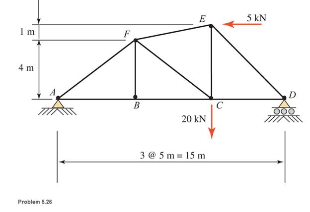
Chapter 5, Problem 5.26SP
Calculate the forces in all members of the trusses shown, using the method of joints.
Expert Solution & Answer
Want to see the full answer?
Check out a sample textbook solution
Students have asked these similar questions
Qu 5 Determine the carburizing time necessary to achieve a carbon concentration of 0.30 wt% at a position 4 mm into an iron carbon alloy that initially contains 0.10 wt% C. The surface concentration is to be maintained at 0.90 wt% C, and the treatment is to be conducted at 1100°C. Use the data for the diffusion of
carbon into y-iron: Do = 2.3 x10⁻⁵ m2/s and Qd = 148,000 J/mol. Express your answer in hours to three significant figures.
show all work step by step problems formula material science
(Read Question)
In figure A, the homogeneous rod of constant cross section is attached to unyielding supports. In figure B, a homogeneous bar with a cross-sectional area of 600 mm2 is attached to rigid supports. The bar carries the axial loads P1 = 20 kN and P2 = 60 kN, as shown.1. In figure A, derive the expression that calculates the reaction R1 in terms of P, and the given dimensions.2. In figure B, calculate the reaction (kN) at A.3. In figure B, calculate the maximum axial stress (MPa) in the rod.
Chapter 5 Solutions
Applied Statics and Strength of Materials (6th Edition)
Ch. 5 - through 5.7 Calculate the forces in all members of...Ch. 5 - Calculate the forces in all members of the trusses...Ch. 5 - Calculate the forces in all members of the trusses...Ch. 5 - Calculate the forces in all members of the trusses...Ch. 5 - Calculate the forces in all members of the trusses...Ch. 5 - Calculate the forces in all members of the trusses...Ch. 5 - Calculate the forces in all members of the trusses...Ch. 5 - Determine the forces in members CD, DH, and HI for...Ch. 5 - Determine the forces in members BC, BE, and FE for...Ch. 5 - Determine the forces in members BC, CH, and CG in...
Ch. 5 - For the Howe roof truss shown, determine the...Ch. 5 - Determine the forces in members DE, CE, and BC in...Ch. 5 - Calculate the forces in members BC, BG, and FG for...Ch. 5 - Determine the forces in members CD, BD, BE, and CB...Ch. 5 - A pin-connected A-frame supports a load, as shown....Ch. 5 - Determine the pin reactions at pins A, B, and C in...Ch. 5 - Calculate the pin reactions at each of the pins in...Ch. 5 - A bracket is pin connected at points A, B, and D...Ch. 5 - A pin-connected frame is loaded, as shown....Ch. 5 - The cylinder shown has a mass of 500 kg. Determine...Ch. 5 - A simple frame is pin connected at points A, B,...Ch. 5 - Using the method of sections, determine the forces...Ch. 5 - Using the method of sections, determine the forces...Ch. 5 - through 5.31 Calculate the forces in all members...Ch. 5 - Calculate the forces in all members of the trusses...Ch. 5 - Calculate the forces in all members of the trusses...Ch. 5 - Calculate the forces in all members of the trusses...Ch. 5 - Calculate the forces in all members of the trusses...Ch. 5 - Calculate the forces in all members of the trusses...Ch. 5 - Calculate the forces in all members of the trusses...Ch. 5 - Calculate the forces in all members of the trusses...Ch. 5 - For Problems 5.32 through 5.38, calculate the...Ch. 5 - For Problem 5.32 through 5.38, Calculate the...Ch. 5 - For Problems 5.32 through 5.38, calculate the...Ch. 5 - For Problems 5.32 through 5.38, calculate the...Ch. 5 - For Problem 5.32 through 5.38 , Calculate the...Ch. 5 - For Problems 5.32 through 5.38, calculate the...Ch. 5 - For Problems 5.32 through 5.38, calculate the...Ch. 5 - A pin-connected crane framework is loaded and...Ch. 5 - Calculate the pin reactions at pins A, B, and D in...Ch. 5 - Determine the pin reactions at pins A, B, and C in...Ch. 5 - The wall bracket shown is pin-connected at points...Ch. 5 - Calculate the pin reactions at each of the pins in...Ch. 5 - The A-frame shown is pin-connected at A,B,C, and...Ch. 5 - The tongs shown are used to grip an object. For an...Ch. 5 - A toggle joint is a mechanism by which a...Ch. 5 - In the toggle joint of Problem 5.46 , assume that...Ch. 5 -
Knowledge Booster


Learn more about
Need a deep-dive on the concept behind this application? Look no further. Learn more about this topic, mechanical-engineering and related others by exploring similar questions and additional content below.Similar questions
- (Read image)arrow_forward(Read Image)arrow_forwardM16x2 grade 8.8 bolts No. 25 C1- Q.2. The figure is a cross section of a grade 25 cast-iron pressure vessel. A total of N, M16x2.0 grade 8.8 bolts are to be used to resist a separating force of 160 kN. (a) Determine ks, km, and C. (b) Find the number of bolts required for a load factor of 2 where the bolts may be reused when the joint 19 mm is taken apart. (c) with the number of bolts obtained in (b), determine the realized load factor for overload, the yielding factor of safety, and the separation factor of safety. 19 mmarrow_forward
- Problem4. The thin uniform disk of mass m = 1-kg and radius R = 0.1m spins about the bent shaft OG with the angular speed w2 = 20 rad/s. At the same time, the shaft rotates about the z-axis with the angular speed 001 = 10 rad/s. The angle between the bent portion of the shaft and the z-axis is ẞ = 35°. The mass of the shaft is negligible compared to the mass of the disk. a. Find the angular momentum of the disk with respect to point G, based on the axis orientation as shown. Include an MVD in your solution. b. Find the angular momentum of the disk with respect to point O, based on the axis orientation as shown. (Note: O is NOT the center of fixed-point rotation.) c. Find the kinetic energy of the assembly. z R R 002 2R x Answer: H = -0.046ĵ-0.040 kg-m²/sec Ho=-0.146-0.015 kg-m²/sec T 0.518 N-m =arrow_forwardProblem 3. The assembly shown consists of a solid sphere of mass m and the uniform slender rod of the same mass, both of which are welded to the shaft. The assembly is rotating with angular velocity w at a particular moment. Find the angular momentum with respect to point O, in terms of the axes shown. Answer: Ñ。 = ½mc²wcosßsinßĵ + (}{mr²w + 2mb²w + ½ mc²wcos²ß) k 3 m r b 2 C لا marrow_forwardOnly question 2arrow_forward
- Only question 1arrow_forwardOnly question 3arrow_forwardI have Euler parameters that describe the orientation of N relative to Q, e = -0.7071*n3, e4 = 0.7071. I have Euler parameters that describe the orientation of U relative to N, e = -1/sqrt(3)*n1, e4 = sqrt(2/3). After using euler parameter rule of successive rotations, I get euler parameters that describe the orientation of U relative to Q, e = -0.4082*n1 - 0.4082*n2 - 0.5774*n3. I need euler parameters that describe the orientation of U relative to Q in vector basis of q instead of n. How do I get that?arrow_forward
- Describe at least 4 processes in engineering where control charts are (or should be) appliedarrow_forwardDescribe at least two (2) processes where control charts are (or should be) applied.arrow_forwardProblem 3: A cube-shaped spacecraft is in a circular Earth orbit. Let N (n,) be inertial and the spacecraft is denoted S (ŝ₁). The spacecraft is described such that ¯½º = J ŝ₁ŝ₁ + J ŝ₂§₂ + J §¸Ŝ3 Location of the spacecraft in the orbit is determined by the orbit-fixed unit vectors ê, that are oriented by the angle (Qt), where is a constant angular rate. 52 €3 3> 2t 55 Λ Из At the instant when Qt = 90°, the spacecraft S is oriented relative to the orbit such that 8₁ = 0° Space-three 1-2-3 angles 0₂ = 60° and ES = $₂ rad/s 0₁ = 135° (a) At this instant, determine the direction cosine matrix that describes the orientation of the spacecraft with respect to the inertial frame N.arrow_forward
arrow_back_ios
SEE MORE QUESTIONS
arrow_forward_ios
Recommended textbooks for you
 International Edition---engineering Mechanics: St...Mechanical EngineeringISBN:9781305501607Author:Andrew Pytel And Jaan KiusalaasPublisher:CENGAGE L
International Edition---engineering Mechanics: St...
Mechanical Engineering
ISBN:9781305501607
Author:Andrew Pytel And Jaan Kiusalaas
Publisher:CENGAGE L
Engineering Basics - Statics & Forces in Equilibrium; Author: Solid Solutions - Professional Design Solutions;https://www.youtube.com/watch?v=dQBvQ2hJZFg;License: Standard YouTube License, CC-BY