
Applied Statics and Strength of Materials (6th Edition)
6th Edition
ISBN: 9780133840544
Author: George F. Limbrunner, Craig D'Allaird, Leonard Spiegel
Publisher: PEARSON
expand_more
expand_more
format_list_bulleted
Concept explainers
Videos
Question
thumb_up100%
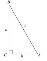
Chapter 1, Problem 1.1P
a.
To determine
The side c of the triangle.
a.
Expert Solution
Answer to Problem 1.1P
Explanation of Solution
Given:
The triangle is
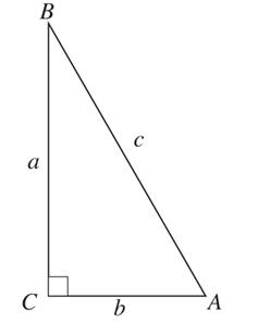
And the sides are
Concept Used:
Pythagoras theorem,
Calculation:
Using Pythagoras theorem,
Conclusion:
Therefore, the side
b.
To determine
The side b of the triangle.
b.
Expert Solution
Answer to Problem 1.1P
Explanation of Solution
Given:
The triangle is
And the sides are
Concept Used:
Pythagoras theorem,
Calculation:
Conclusion:
Therefore, the side
Want to see more full solutions like this?
Subscribe now to access step-by-step solutions to millions of textbook problems written by subject matter experts!
schedule05:30
Students have asked these similar questions
reaction at a is 1.6 wL (pos)
handwritten solutions only please. correct answers upvoted
1
8
4
Add numbers so that the sum of any
row or column equals .30 Use only
these numbers:
.1.2.3.4.5.6.10.11.12.12.13.14.14
Uppgift 2 (9p)
I77777
20 kN
10 kN/m
4
[m]
2
2
Bestäm tvärkrafts- och momentdiagram för balken i figuren ovan. Extrempunkter ska anges
med både läge och värde i diagrammen.
Chapter 1 Solutions
Applied Statics and Strength of Materials (6th Edition)
Ch. 1 - Prob. 1.1PCh. 1 - In the right triangle ABC shown, c = 25 ft and...Ch. 1 - Determine the length of side a and the meausre of...Ch. 1 - A 28-ft-long ladder leaning against a wall makes...Ch. 1 - Two legs of a right triangle are 6 ft and 10 ft....Ch. 1 - In the roof truss shown determine the lengths of...Ch. 1 - A level scaffold s to be supported at the center...Ch. 1 - A wanderer hikes due east for 2 mi, then southeast...Ch. 1 - Freehand sketch the following triangles and solve...Ch. 1 - One side of a triangular lot is 100 ft and the...
Ch. 1 - A box containing 8 shock absorbers and 10 brake...Ch. 1 - Prob. 1.12PCh. 1 - Express 0.015 ton (a) in pounds (lb) and (b) in...Ch. 1 - Express 5 mi (a) in yards (yd) and (b) in feet...Ch. 1 - Express 60 miles per hour (mph) in units of feet...Ch. 1 - Find the number of square rods in one acre.Ch. 1 - A reservoir contains an estimated 125 billion...Ch. 1 - Convert the following: a. 27 ft 734 in. to...Ch. 1 - 1.19 A water system of 2 in (inside diameter)...Ch. 1 - The soil pressure under a concrete footing is...Ch. 1 - Using Table 1 , establish your height in...Ch. 1 - The dimensions on a baseball field are as follows:...Ch. 1 - Convert the following quantities from U.S....Ch. 1 - Convert the following quantities to SI units of...Ch. 1 - Convert the following quantities to SI units of...Ch. 1 - Convert the following quantities to the designated...Ch. 1 - 1.27 Rework Problem 1.19 using an inside pipe...Ch. 1 - A spherical tank has a radius of 27 in. Find the...Ch. 1 - 1.29 A ladder rests against a vertical wall at a...Ch. 1 - A surveyor measures a zenith angle of 70° 03’20”...Ch. 1 - The tower of a tower crane casts a shadow (on...Ch. 1 - 1.32 From the top of a 30-ft building, the angle...Ch. 1 - Two planes, starting from airport X, fly for 2 hr,...Ch. 1 - Rework Problem 1.31 assuming that the ground...Ch. 1 - An Egyptian pyramid has a square base and...Ch. 1 - Two observation towers A and B are located 300 ft...Ch. 1 - Two people fishing from rowboats on a lake are 100...Ch. 1 - What is the average speed in miles per hour (mph)...Ch. 1 - The volume flow of a river is expressed as 5000...Ch. 1 - A 55-gal drum filled with sand weighs 816 lb. The...Ch. 1 - The total area to be occupied by a building and a...Ch. 1 - An electronic distance measurement device (EDM) is...
Knowledge Booster


Learn more about
Need a deep-dive on the concept behind this application? Look no further. Learn more about this topic, mechanical-engineering and related others by exploring similar questions and additional content below.Similar questions
- **Problem 8-45.** The man has a mass of 60 kg and the crate has a mass of 100 kg. If the coefficient of static friction between his shoes and the ground is \( \mu_s = 0.4 \) and between the crate and the ground is \( \mu_c = 0.3 \), determine if the man is able to move the crate using the rope-and-pulley system shown. **Diagram Explanation:** The diagram illustrates a scenario where a man is attempting to pull a crate using a rope-and-pulley system. The setup is as follows: - **Crate (C):** Positioned on the ground with a rope attached. - **Rope:** Connects the crate to a pulley system and extends to the man. - **Pulley on Tree:** The rope runs over a pulley mounted on a tree which redirects the rope. - **Angles:** - The rope between the crate and tree forms a \(30^\circ\) angle with the horizontal. - The rope between the tree and the man makes a \(45^\circ\) angle with the horizontal. - **Man (A):** Pulling on the rope with the intention of moving the crate. This arrangement tests the…arrow_forwardplease solve this problems follow what the question are asking to do please show me step by steparrow_forwardplease first write the line action find the forces and them solve the problem step by steparrow_forward
- please solve this problem what the problem are asking to solve please explain step by step and give me the correct answerarrow_forwardplease help me to solve this problem step by steparrow_forwardplease help me to solve this problem and determine the stress for each point i like to be explained step by step with the correct answerarrow_forward
- please solve this problem for me the best way that you can explained to solve please show me the step how to solvearrow_forwardplese solbe this problem and give the correct answer solve step by step find the forces and line actionarrow_forwardplease help me to solve this problems first write the line of action and them find the forces {fx=0: fy=0: mz=0: and them draw the shear and bending moment diagram. please explain step by steparrow_forward
- please solve this problem step by step like human and give correct answer step by steparrow_forwardPROBLEM 11: Determine the force, P, that must be exerted on the handles of the bolt cutter. (A) 7.5 N (B) 30.0 N (C) 52.5 N (D) 300 N (E) 325 N .B X 3 cm E 40 cm cm F = 1000 N 10 cm 3 cm boltarrow_forwardUsing the moment-area theorems, determine a) the rotation at A, b) the deflection at L/2, c) the deflection at L/4. (Hint: Use symmetry for Part a (θA= - θB, or θC=0), Use the rotation at A for Parts b and c. Note that all deformations in the scope of our topics are small deformation and for small θ, sinθ=θ).arrow_forward
arrow_back_ios
SEE MORE QUESTIONS
arrow_forward_ios
Recommended textbooks for you
 Elements Of ElectromagneticsMechanical EngineeringISBN:9780190698614Author:Sadiku, Matthew N. O.Publisher:Oxford University Press
 Mechanics of Materials (10th Edition)Mechanical EngineeringISBN:9780134319650Author:Russell C. HibbelerPublisher:PEARSON
 Thermodynamics: An Engineering ApproachMechanical EngineeringISBN:9781259822674Author:Yunus A. Cengel Dr., Michael A. BolesPublisher:McGraw-Hill Education
 Control Systems EngineeringMechanical EngineeringISBN:9781118170519Author:Norman S. NisePublisher:WILEY
 Mechanics of Materials (MindTap Course List)Mechanical EngineeringISBN:9781337093347Author:Barry J. Goodno, James M. GerePublisher:Cengage Learning
 Engineering Mechanics: StaticsMechanical EngineeringISBN:9781118807330Author:James L. Meriam, L. G. Kraige, J. N. BoltonPublisher:WILEY
Elements Of Electromagnetics
Mechanical Engineering
ISBN:9780190698614
Author:Sadiku, Matthew N. O.
Publisher:Oxford University Press
Mechanics of Materials (10th Edition)
Mechanical Engineering
ISBN:9780134319650
Author:Russell C. Hibbeler
Publisher:PEARSON
Thermodynamics: An Engineering Approach
Mechanical Engineering
ISBN:9781259822674
Author:Yunus A. Cengel Dr., Michael A. Boles
Publisher:McGraw-Hill Education
Control Systems Engineering
Mechanical Engineering
ISBN:9781118170519
Author:Norman S. Nise
Publisher:WILEY
Mechanics of Materials (MindTap Course List)
Mechanical Engineering
ISBN:9781337093347
Author:Barry J. Goodno, James M. Gere
Publisher:Cengage Learning
Engineering Mechanics: Statics
Mechanical Engineering
ISBN:9781118807330
Author:James L. Meriam, L. G. Kraige, J. N. Bolton
Publisher:WILEY
Mechanical Engineering: Centroids & Center of Gravity (1 of 35) What is Center of Gravity?; Author: Michel van Biezen;https://www.youtube.com/watch?v=Tkyk-G1rDQg;License: Standard Youtube License