
Applied Statics and Strength of Materials (6th Edition)
6th Edition
ISBN: 9780133840544
Author: George F. Limbrunner, Craig D'Allaird, Leonard Spiegel
Publisher: PEARSON
expand_more
expand_more
format_list_bulleted
Concept explainers
Videos
Textbook Question
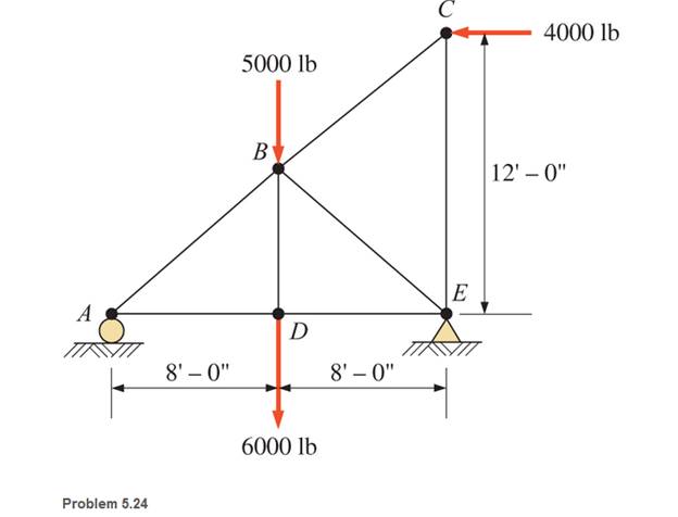
Chapter 5, Problem 5.24SP
through 5.31 Calculate the forces in all members of the trusses shown, using the method of joints.
Expert Solution & Answer

Learn your wayIncludes step-by-step video

schedule14:14
Students have asked these similar questions
For the truss shown below:
1. Calculate the force in all members (Using the method of joints).
2. Indicate if members AB, BE, and DE are compression or tension members.
3. Calculate the force in member BE (Using the method of sections).
4. Compare the results for part (1) and part (2)
4 m
A
3 m
12 kN
D
B
3 m
E 3 kN
C
III. Construct the internal force diagrams of the following structure by using the method
of superposition segment by segment
1. Bending moment and shear force
3kN- m
E
2.5m
2.5m
2m
to
2. Bending moment
Fr
a
Problem 7
Compute the reaction forces in B and D.
Hint: in this case, since you have to determine the external reactions only, you can consider the
truss as a single rigid body
4.5 m
4.5 m
B
2.8 m
A
8.4 kN
8.4 kN
Chapter 5 Solutions
Applied Statics and Strength of Materials (6th Edition)
Ch. 5 - through 5.7 Calculate the forces in all members of...Ch. 5 - Calculate the forces in all members of the trusses...Ch. 5 - Calculate the forces in all members of the trusses...Ch. 5 - Calculate the forces in all members of the trusses...Ch. 5 - Calculate the forces in all members of the trusses...Ch. 5 - Calculate the forces in all members of the trusses...Ch. 5 - Calculate the forces in all members of the trusses...Ch. 5 - Determine the forces in members CD, DH, and HI for...Ch. 5 - Determine the forces in members BC, BE, and FE for...Ch. 5 - Determine the forces in members BC, CH, and CG in...
Ch. 5 - For the Howe roof truss shown, determine the...Ch. 5 - Determine the forces in members DE, CE, and BC in...Ch. 5 - Calculate the forces in members BC, BG, and FG for...Ch. 5 - Determine the forces in members CD, BD, BE, and CB...Ch. 5 - A pin-connected A-frame supports a load, as shown....Ch. 5 - Determine the pin reactions at pins A, B, and C in...Ch. 5 - Calculate the pin reactions at each of the pins in...Ch. 5 - A bracket is pin connected at points A, B, and D...Ch. 5 - A pin-connected frame is loaded, as shown....Ch. 5 - The cylinder shown has a mass of 500 kg. Determine...Ch. 5 - A simple frame is pin connected at points A, B,...Ch. 5 - Using the method of sections, determine the forces...Ch. 5 - Using the method of sections, determine the forces...Ch. 5 - through 5.31 Calculate the forces in all members...Ch. 5 - Calculate the forces in all members of the trusses...Ch. 5 - Calculate the forces in all members of the trusses...Ch. 5 - Calculate the forces in all members of the trusses...Ch. 5 - Calculate the forces in all members of the trusses...Ch. 5 - Calculate the forces in all members of the trusses...Ch. 5 - Calculate the forces in all members of the trusses...Ch. 5 - Calculate the forces in all members of the trusses...Ch. 5 - For Problems 5.32 through 5.38, calculate the...Ch. 5 - For Problem 5.32 through 5.38, Calculate the...Ch. 5 - For Problems 5.32 through 5.38, calculate the...Ch. 5 - For Problems 5.32 through 5.38, calculate the...Ch. 5 - For Problem 5.32 through 5.38 , Calculate the...Ch. 5 - For Problems 5.32 through 5.38, calculate the...Ch. 5 - For Problems 5.32 through 5.38, calculate the...Ch. 5 - A pin-connected crane framework is loaded and...Ch. 5 - Calculate the pin reactions at pins A, B, and D in...Ch. 5 - Determine the pin reactions at pins A, B, and C in...Ch. 5 - The wall bracket shown is pin-connected at points...Ch. 5 - Calculate the pin reactions at each of the pins in...Ch. 5 - The A-frame shown is pin-connected at A,B,C, and...Ch. 5 - The tongs shown are used to grip an object. For an...Ch. 5 - A toggle joint is a mechanism by which a...Ch. 5 - In the toggle joint of Problem 5.46 , assume that...Ch. 5 -
Additional Engineering Textbook Solutions
Find more solutions based on key concepts
The data shown in the following graph was collected during testing of an electromagnetic mass driver. The energ...
Thinking Like an Engineer: An Active Learning Approach (3rd Edition)
1.1 Convert 1250 millimeters to meters.
Applied Fluid Mechanics (7th Edition)
State if these members are in tension or compression. Probs. 6-32
Engineering Mechanics: Statics
The moment of force about point O.
Engineering Mechanics: Statics & Dynamics (14th Edition)
If crank OA rotates with an angular velocity of = 12 rid/s, determine the velocity of piston B and the angular...
Engineering Mechanics: Dynamics (14th Edition)
Determine the tension in the cables in order to support the 100-kg crate in the equilibrium position shown.
INTERNATIONAL EDITION---Engineering Mechanics: Statics, 14th edition (SI unit)
Knowledge Booster


Learn more about
Need a deep-dive on the concept behind this application? Look no further. Learn more about this topic, mechanical-engineering and related others by exploring similar questions and additional content below.Similar questions
- Problem 6. The truss below was designed to hang a one-of-a-kind sign that weighs 1000 lb. The sign is attached to the truss by two cables at attached at pin H of the truss and a rod that is attached at pin G of the truss; the rod is pin connected at both ends. The truss is attached to the wall by a pin at A and another cable (there are 3 cables at point H). Find the internal force in members AE, CH, EC, and EF. H cable cable 8' pin B с cable 8' 3' 3' rod E F 6' 1' 1.5' 2'> sign: 6'x 8', 1000 lbarrow_forwardFor the next Trusses, compute the axial forces in the selected sections. Compare the result with the method of joints. (Check the image for the trusses)arrow_forward3. For the truss shown below, find the internal force of all members using method of sections. 120 kN 4.5 m 3 m 1.5 m 2 m 2 m 2 m 60 kNarrow_forward
- Problem 2 (Pro 3.25 Textbook): Identify the zero-force members in the trusses belowarrow_forwardFind forces in truss using methods of joints. Is it possible to solve the problem using method of sections. Show section lines on the body. Draw the FBD for the truss and calculate reactionsarrow_forward2) A force, P, is applied to the truss shown to the right. First, determine the support reactions at C and F. Determine the force in member AB in terms of the A В applied force P (specify tension or compression). You must do this problem: (a) first, using method of joints, (b) second, using method of sections. (For part (a), plan ahead: what is the best joint to start with, so you can minimize the number of joints you need to analyze?) (FYI, you can do this problem without a calculator problem.) Ans. C, = 2P/3 (↑), Fx = 0, F, = P/3 (↑) FAB = P/2 (C) 4 m C F E OMONO P 3 m 3 m 3 marrow_forward
- 1) A Warren bridge truss is shown to the below. (a) Determine the support reactions at A and K. (b) Determine the force in members CE, DE, and DF using method of joints. (c) Determine the force in members CE, DE, and DF using method of sections. (Note: A is a roller and K is a pin.) Ans: Ay = 8400 lb (1), K, = 0, Ky = 3600 lb (T), FCE = 8000 lb (T), FDE = 2600 lb (T), FDF = 9000 lb (C). [Intermediate answers for method of joints: FAB = 9100 lb (C), FAC = 3500 lb (T), FBC = 9100 lb (T), FBD = 7000 lb (C), FcD = 2600 lb (C)I %3D 6.25 ft 12.5 ft, 12.5 ft 12.5 ft, 12.5 ft В F H 15 ft K E 12.5 ft 12.5 ft 12.5 ft' 12.5 ft' 12.5 ft 6000 lb 6000 lbarrow_forwardProblem 5.2 Calculate the forces in all members of the trusses shown using the method of joints. Please show all work and units. Thanksarrow_forwardFor the truss loaded as shown in the figure, determine; a. the magnitude and type of forces in members AB, AC, BC, BD, BE, CE, DE, DF, DG and E by method of joints. b. the magnitude and type of forces in members FH, GH, GI, HJ, JI and IK by method of sections.arrow_forward
- (ENGINERRING MECHANICS) ALREADY ANSWERED IN BARTLEBY. PLEASE DRAW THE FREE-BODY DUAGRAM UPVOTE WILL BE GIVEN. PLEASE WRITE THE COMPLETE SOLUTIONS. SOLVE IN 6 DECIMAL PLACES. BOX THE FINAL ANSWERS.)arrow_forwardNonearrow_forwardFind forces in all truss using method of sections Draw FBD for truss and calculate reactionsarrow_forward
arrow_back_ios
SEE MORE QUESTIONS
arrow_forward_ios
Recommended textbooks for you
 International Edition---engineering Mechanics: St...Mechanical EngineeringISBN:9781305501607Author:Andrew Pytel And Jaan KiusalaasPublisher:CENGAGE L
International Edition---engineering Mechanics: St...
Mechanical Engineering
ISBN:9781305501607
Author:Andrew Pytel And Jaan Kiusalaas
Publisher:CENGAGE L
Engineering Basics - Statics & Forces in Equilibrium; Author: Solid Solutions - Professional Design Solutions;https://www.youtube.com/watch?v=dQBvQ2hJZFg;License: Standard YouTube License, CC-BY