
Steel Design (Activate Learning with these NEW titles from Engineering!)
6th Edition
ISBN: 9781337094740
Author: Segui, William T.
Publisher: Cengage Learning
expand_more
expand_more
format_list_bulleted
Videos
Textbook Question
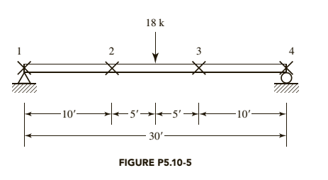
Chapter 5, Problem 5.10.5P
The given beam is laterally supported at the ends and at the
a. Use LRFD.
b. Use ASD.
Expert Solution & Answer

Trending nowThis is a popular solution!

Students have asked these similar questions
A structure is an intersecting hip roof with the main hip roof outside dimensions being 73 ft long and the width being 30 ft wide. The intersection portion extends 20 ft beyond the 30-ft side, and the intersecting portion is 20 ft wide. The overhang is 2 ft 6 in. and the slope is 5:12. The rafters are 16 in. on center. Based on the information provided, what is the total length of the common rafters in linear feet?
How many board feet is 200 lnft of 2 in. × 6 in wood studs.
Example: Determine the minimum slope in the upper reach of a chute section of
30 m width. The range of discharge is 150 to 2000 m³/sec. n = 0.015.
Chapter 5 Solutions
Steel Design (Activate Learning with these NEW titles from Engineering!)
Ch. 5 - Prob. 5.2.1PCh. 5 - Prob. 5.2.2PCh. 5 - Verify the value of Zx for a W1850 that is...Ch. 5 - Prob. 5.2.4PCh. 5 - Prob. 5.4.1PCh. 5 - Prob. 5.4.2PCh. 5 - Determine the smallest value of yield stress Fy,...Ch. 5 - Prob. 5.5.1PCh. 5 - Prob. 5.5.2PCh. 5 - Prob. 5.5.3P
Ch. 5 - Prob. 5.5.4PCh. 5 - Prob. 5.5.5PCh. 5 - Prob. 5.5.6PCh. 5 - Prob. 5.5.7PCh. 5 - Prob. 5.5.8PCh. 5 - Prob. 5.5.9PCh. 5 - If the beam in Problem 5.5-9 i5 braced at A, B,...Ch. 5 - Prob. 5.5.11PCh. 5 - Prob. 5.5.12PCh. 5 - Prob. 5.5.13PCh. 5 - Prob. 5.5.14PCh. 5 - Prob. 5.5.15PCh. 5 - Prob. 5.5.16PCh. 5 - Prob. 5.6.1PCh. 5 - Prob. 5.6.2PCh. 5 - Prob. 5.6.3PCh. 5 - Prob. 5.6.4PCh. 5 - Compute the nominal shear strength of an M107.5 of...Ch. 5 - Compute the nominal shear strength of an M1211.8...Ch. 5 - Prob. 5.8.3PCh. 5 - Prob. 5.8.4PCh. 5 - Prob. 5.10.1PCh. 5 - Prob. 5.10.2PCh. 5 - Same as Problem 5.10-2, except that lateral...Ch. 5 - Prob. 5.10.4PCh. 5 - The given beam is laterally supported at the ends...Ch. 5 - Prob. 5.10.6PCh. 5 - Prob. 5.10.7PCh. 5 - Prob. 5.11.1PCh. 5 - Prob. 5.11.2PCh. 5 - Prob. 5.11.3PCh. 5 - Prob. 5.11.4PCh. 5 - Prob. 5.11.5PCh. 5 - Prob. 5.11.6PCh. 5 - Prob. 5.11.7PCh. 5 - Prob. 5.11.8PCh. 5 - Prob. 5.11.9PCh. 5 - Prob. 5.12.1PCh. 5 - Prob. 5.12.2PCh. 5 - Prob. 5.12.3PCh. 5 - Prob. 5.13.1PCh. 5 - Prob. 5.13.2PCh. 5 - Prob. 5.14.1PCh. 5 - Prob. 5.14.2PCh. 5 - Prob. 5.14.3PCh. 5 - Prob. 5.14.4PCh. 5 - Prob. 5.15.1PCh. 5 - Prob. 5.15.2PCh. 5 - Prob. 5.15.3PCh. 5 - Prob. 5.15.4PCh. 5 - Prob. 5.15.5PCh. 5 - Prob. 5.15.6PCh. 5 - Prob. 5.15.7PCh. 5 - Same as Problem 5.15-7, except that the sag rods...
Knowledge Booster


Learn more about
Need a deep-dive on the concept behind this application? Look no further. Learn more about this topic, civil-engineering and related others by exploring similar questions and additional content below.Similar questions
- 1. Zinc is an important trace nutrient for photosynthetic organisms (e.g., phytoplankton) in sea water. Calculate the speciation of zinc (Zn(II)) in seawater assuming Zn(II) TOT = 5 x 10⁻⁸ M. Provide a list of the metal-ligand complexes and their corresponding stability Constants that you will include in your calculation. If you decide to exclude any of the complexes for which stability constants are provided in Table 9.4, please list these separately and explain your rationale. b. Compute the concentrations of the metal-ligand complexes identified in part a. c. Compute the activities of the metal-ligand complexes using the concentrations calculated in part b and using the data in Table 9.6B to calculate the activity coefficients. (Note—you likely already have a spreadsheet where you calculated activity coefficients from week 3!)arrow_forwardQ.2 The required design span for the beam given in Q.1 is increased to 18 ft. The design loads are the same as given in Q.1 Check the adequacy of a 10"x16" 10 Caribbean Pitch Pine – (Select Structural) for this these design conditions.arrow_forwardThe timber floor framing for a building comprise floor joists using 2" wide nominal lumber is to be constructed as shown in Fig. 1. The Dead load (D) = 26 lbs./ft² (inclusive of joists and flooring) and the live load L= 40 lbs./ft². Lateral torsional buckling is prevented for all members and normal service conditions and temperatures are expected. (i) Design the floor joists using 2" wide nominal lumber using Southern Pine No. 1 (ii) Design the floor beams using Caribbean Pitch Pine (Select Structural). (Assume a 8" x 14” trial section to estimate beam self-weight for your initial design). Density of Caribbean Pitch Pine = 50 lbs/ft³ (800 kN/m³).arrow_forward
- P12.38 WP At a point on the free surface of a stressed body, a normal stress of 64 MPa (C) and an unknown positive shear stress exist on a horizontal plane. One principal stress at the point is 8 MPa (C). The absolute maximum shear stress at the point has a magnitude of 95 MPa. Determine the unknown stresses on the horizontal and vertical planes and the unknown principal stress at the point.arrow_forwardA pile group of 25 piles has to be proportioned in a uniform pattern in soft clay with equal spacing in all directions. Assuming the value of cu to be constant throughout the depth of the piles, determine the optimum value of spacing of piles in the group. Assume a = 0.7. Neglect point bearing effect, and assume the piles to be circular.arrow_forwardExample 5 By using the yield line theory, determine the moment (m) for an isotropic reinforced concrete two-way slab (supports on two S.S sides shown in figure under the load (P) (all dimensions are in mm). Solve by using equilibrium method m m 3000 2000 2000arrow_forward
- A +7.5% grade meets a horizontal grade on a section of a rural mountainous highway. If the length of the crest vertical curve formed in that section is 300 ft long, determine the safe operating speed on the highway.arrow_forwardA sawn timber beam of dimensions 8"x14" has is required for a span of 16 ft. The uniformly distributed loads are Dead (D) = 350 lbs./ft and live (L) = 400 lbs./ft. The dead load includes the beam self-weight and lateral torsional buckling is prevented. The beam is to be used in an indoor environment (MC > 19º) in normal temperatures. Using Caribbean Pitch Pine (Select Structural), check that the section chosen is adequate.arrow_forward2. Find the moment of inertia and radius of gyration about the coordinate axes of a thin rectangular plate of constant density bounded by the lines x=3 and y = 3 in the first quadrant.arrow_forward
- Vehicle begin to arrive at a parking lot at 6:00 am at a rate of 8 per minute. No vehicles arrivefrom from 6:20 to 6:30 am. From 6:30 am on vehicle arrive at a rate of 2 veh/min. The parkinglot attendant processes incoming vehicles at a rate of 4 veh/min throughout day. AssumingD/D/1 queue, determine total vehicle delayarrow_forwardA cantilever beam 12 ft long supports a uniform service superimposed deadload of 1 kip/ft, and a concentrated service live load of 14 kip at the free end. Theconcrete compressive strength is 4 ksi, and the steel yield strength is 60 ksi. Thebeam section at the support is shown. Find the adequacy of the section inresisting bending moment at the support.arrow_forwardu(t) (Uss) -1 a/w = 1.0 M 1 2 3 Tarrow_forward
arrow_back_ios
SEE MORE QUESTIONS
arrow_forward_ios
Recommended textbooks for you
 Steel Design (Activate Learning with these NEW ti...Civil EngineeringISBN:9781337094740Author:Segui, William T.Publisher:Cengage Learning
 Materials Science And Engineering PropertiesCivil EngineeringISBN:9781111988609Author:Charles GilmorePublisher:Cengage Learning
Steel Design (Activate Learning with these NEW ti...
Civil Engineering
ISBN:9781337094740
Author:Segui, William T.
Publisher:Cengage Learning
Materials Science And Engineering Properties
Civil Engineering
ISBN:9781111988609
Author:Charles Gilmore
Publisher:Cengage Learning
The History of Iron and Steel; Author: Real Engineering;https://www.youtube.com/watch?v=7E__zqy6xcw;License: Standard Youtube License