(a)
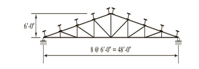
The adequacy of the W 6 X12 beam for use as purlin using LRFD method.
Answer to Problem 5.5.16P
The beam is adequate to be used for purlin.
Explanation of Solution
Given:
A truss with a roof system supporting a total gravity load of 40 psf of roof surface, half dead load and half snow. Spacing = 10 ft on centers.

Calculation:
Let’s calculate the nominal flexural strength about the X and Y axes.
Determine the strong axis bending strength. As neither the beam design charts nor the Z tables include shapes under W8 compute the flexural strength of W 6 X12. As there is no foot note to indicate otherwise the shape is compact.
We need to determine what controls the lateral torsional buckling.
Computing the values of
Substitute the values from the AISC Manual as
Substitute the values from the AISC Manual as
Now calculate the plastic moment for the section, we have
Where,
Substitute the values from the ASIC manual, we have
Let’s compare the values
Which implies that the strength is governed by inelastic Lateral- Torsional Buckling.
Compute the nominal strength of beam using the equation given as follows:
Substitute the values from the ASIC manual, we have
For the Y − axis, there is no flange buckling since the shape is compact.
Calculate the flexural strength about y- axis as:
Where,
Now, calculating the plastic moment of section about minor principal axis as:
Substitute the values, we have
Calculate the flexural strength about y axis, we have
Checking the upper limit using the following :
Substitute the values, we have
As the inequality is satisfied then the its OK.
Now using the LRFD method.
Following equation must be satisfied in order to know adhere to AISC specifications.
Where,
Now we need to find the values to substitute them
Where,
Where,
Where
As it is been given that half of load is dead load and half is snow load.
Therefore, as per the given conditions
Where,
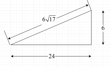
Following is the diagram from which we can find the value of angles.

Substitute the value for H = 6 ft and
Substitute the values
Substitute,
Find the flexural load about x-axis,
Similarly, for
Where,
Substitute,
Find the flexural load about x-axis,
Now, find the values of
As we have found every value, now we can substitute the values and check the adequacy
The equation is hence satisfied.
Conclusion:
Therefore, the beam is adequate.
(b)
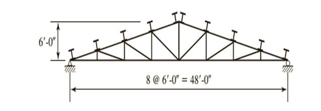
The adequacy of W 6 X12 beam for use as purlin using ASD method.
Answer to Problem 5.5.16P
The beam is adequate to be used for purlin.
Explanation of Solution
Given:
A truss with a roof system supporting a total gravity load of 40 psf of roof surface, half dead load and half snow. Spacing = 10 ft on centers.

Calculation:
Now from Allowable stress design
Where
Now find the value of
Where,
Where,
Where
As it is been given that half of load is dead load and half is snow load.
Therefore, as per the given conditions
Calculate the load on the purlin as follows:
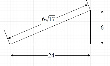
Following is the diagram from which we can find the value of angles.

Where,
Substitute the value for H = 6 ft and
Load on the purlin is as follows:
Substitute the values, we have
Now,
Where, L is the length of the beam and
Where,
Substitute the values, we have
Now find the value of
As we have found every value, now we can substitute the values and check the adequacy
Hence, the equation is satisfied.
Conclusion:
Therefore, the beam is adequate.
Want to see more full solutions like this?
Chapter 5 Solutions
Steel Design (Activate Learning with these NEW titles from Engineering!)
- Deformation of a retaining wall is assumed to be as presented in the figure below. Determine:a) variation of the active and passive pressures on the wall for the presented deformation b) magnitude of the total horizontal force on the right side of the wall.arrow_forward2. a) Consider a cable used for aerial tramway (see figure a). The span is 400 m. The unstretched length of the cable is 402 m. Its mass per unit length is 10kg. The elasticity EA = 10 N. Find the horizontal load on the two ends and the sag d. Determine if the small sag condition is satisfied. b) When a cable car whose mass is 500kg is hung below the cable at a horizontal distance of 100 m from the left end, find the horizontal load on the ends. C) As the car goes along the cable, at which position you will see maximum horizontal load on the two ends?arrow_forwardTwo square surface footings are placed 20 feet apart. Calculate ultimate settlements beneath footing I and at the centerline of the two footings.arrow_forward
- Find the bending moment diagram for. structure drawn below using castigliani's Second theorems. 10kN/m A B 5m 10marrow_forwardDesign the foundation in Problem 3 (find the radius), for the assumptions that the failure isgeneral, sand is dry, loading Q=6000 kN, and the factory of safety is 2.4.arrow_forwardAssume that the moist unit weight of sand in Problem 1 to be 122 lb/ft3, the saturated unit weight of sand 130 and clay 120 lb/ft 3. What should be the thickness of a soil layer of a unit weight of 120 lb/ft 3 that would cause consolidation settlement of 0.1 ft in 100 days?arrow_forward
- Define the allowable bearing capacity of a circular foundation of a radius 2R=10 ft using theTerzaghi's bearing capacity equation for a local failure. In your calculations assume two scenarios:a) that the ground water table matches the bottom of the foundation, and b) that the ground watertable is 6 ft below the bottom of the foundation. Use a factor of safety of 2.8, and the dry unit weightabove the ground water table.arrow_forwardFor the square foundation below determine: a) ultimate settlement and b) settlement after 140days due to consolidation of the clay layer. Base your calculations on the values at the midpoint ofthe layer.arrow_forwardEvaluate all reactions & internalforces using Moment DistributionE=29000ksi I=400in^(4) for all members.arrow_forward
- A silty sand sample failed during a consolidated-undrained triaxial test at F1=280 kPa andF3=170 kPa. With the assumption that c=0 and A=0.65, determine the consolidated-undrainedfriction angle Ncu and a drained friction angle N. If a consolidated-undrained test on such a soil isconducted at a confining pressure F3 =340 kPa, what will be major total and effective stresses andthe pore water pressure at failure? What will be the maximum shear stress J during a "slow" directshear test, if the vertical stress Fv=160 kPa?arrow_forwardCheck the adequacy of a 15ft long A992 W12x65 beam-column shown in figure (1). The axial loads and end moments have been obtained from 2nd order analysis of the gravity loads. The frame and loading are symmetric. Assume that (Cb) is 1.06. PD-85k, PL-220k MD-15k-ft, ML-45k-ft Le-8.6ft MD-18k-ft, ML-52kfarrow_forwardecos y dyarrow_forward
 Steel Design (Activate Learning with these NEW ti...Civil EngineeringISBN:9781337094740Author:Segui, William T.Publisher:Cengage Learning
