
Introductory Circuit Analysis (13th Edition)
13th Edition
ISBN: 9780133923605
Author: Robert L. Boylestad
Publisher: PEARSON
expand_more
expand_more
format_list_bulleted
Concept explainers
Videos
Textbook Question
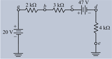
Chapter 5, Problem 41P
For the network in Fig. 5.127 determine the voltages:
Expert Solution & Answer
Want to see the full answer?
Check out a sample textbook solution
Students have asked these similar questions
Q2:
(30 Marks)
Design a DC/DC converter that produce output waveforms that shown in figures below from a
fixed DC source of 20 volts.
Vo (Volt)
14.1
IL (Amp)
13.9
2.25
1.75
† (msec)
Output voltage
0.18
0.2
t (msec)
L
0.214 0.22
Output current
6. Build the circuit shown in Figure 2 below in PSpice. Note that the power supply V1 is a
VSIN power supply in the SOURCE library. Vcc is a VDC supply found in the SOURCE
library. Model this circuit using the Time Domain (Transient) Analysis Type with a Run To
Time of 2 ms.
A. Paste your output graph showing the voltage at the base terminal, collector terminal
and at the load.
B. What is the voltage gain of the circuit? (Compare the voltage amplitude at the base
terminal input (across Rb2) to that at the collector terminal.
C. What happens to the output voltage at the collector terminal if the value of Rb1 is
reduced by a factor of 10 (to 14.7 kn)? Simulate this situation and explain the result.
D. What happens to the output voltage at the collector terminal if the value of Rb1 is
increased by a factor of 3 (to 441 k)? Simulate this situation and explain the result.
Rb1
RC
147k
1k
C2
C1
Q1
Vcc
1u
VOFF = 0
Q2N3904
10Vdc
VAMPL = 0.1V1
1u
FREQ = 2k
R_load
Rb2
Re
AC = 0
250
40k
20
Figure…
The input reactance of 1/2 dipole with radius of 1/30 is given as shown in figure below,
Assuming the wire of dipole is conductor 5.6*107
S/m, determine at f=1 GHz the
a-Loss resistance, b- Radiation efficiency
c-Reflection efficiency when the antenna is
connected to T.L shown in the figure.
Rr
Ro= 50 2
1/4
RL
-j100
[In(l/a) - 1.5]
tan(ẞl)
Chapter 5 Solutions
Introductory Circuit Analysis (13th Edition)
Ch. 5 - For each configuration in Fig. 5.88, find the...Ch. 5 - For each configuration in Fig. 5.89, find the...Ch. 5 - Find the total resistance RT for each...Ch. 5 - Find the total resistance RT for each...Ch. 5 - For each circuit board in Fig. 5.92, �nd the...Ch. 5 - For the circuit in Fig. 5.93, composed of standard...Ch. 5 - For each configuration in Fig. 5.94, determine the...Ch. 5 - Find the resistance R, given the ohmmeter reading...Ch. 5 - What is the ohmmeter reading for each...Ch. 5 - For the series configuration in Fig. 5.97,...
Ch. 5 - For the series configuration in Fig. 5.98,...Ch. 5 - Find the applied voltage necessary to develop the...Ch. 5 - For each network in Fig. 5.100, constructed of...Ch. 5 - For each configuration in Fig. 5.101, what are the...Ch. 5 - For each configuration of Fig. 5.102, find the...Ch. 5 - For the circuit in Fig. 5.103, constructed of...Ch. 5 - Find the unknown quantities for the circuit of...Ch. 5 - Find the unknown quantities for the circuit in...Ch. 5 - Eight holiday lights are connected in series as...Ch. 5 - For the conditions specified in Fig. 5.107,...Ch. 5 - Combine the series voltage sources in Fig. 5.108,...Ch. 5 - Determine the current I and its direction for each...Ch. 5 - Find {he unknown voltage source and resistor for...Ch. 5 - Using Kirchhoffs voltage law, find the unknown...Ch. 5 - Find the current I for the network of Fig. 5.112....Ch. 5 - Using Kirchhoffs voltage law, determine the...Ch. 5 - Using Kirchhoffs voltage law, find the unknown...Ch. 5 - Determine the values of the unknown resistors in...Ch. 5 - For the configuration in Fig. 5.116, with standard...Ch. 5 - Using the voltage divider rule, find the indicated...Ch. 5 - Using the voltage divider rule or Kirchhoffs...Ch. 5 - Using the voltage divider rule or Kirchhoffs...Ch. 5 - Using the information provided, find the unknown...Ch. 5 - Using the voltage divider rule, �nd the unknown...Ch. 5 - Design a voltage divider circuit that will permit...Ch. 5 - Design the voltage divider in Fig. 5.122 such that...Ch. 5 - Find the voltage across each resistor in Fig....Ch. 5 - Design the circuit in Fig. 5.124 such that...Ch. 5 - Determine the voltages Va,Vb, and Vab for the...Ch. 5 - Determine the current I (with direction) and the...Ch. 5 - For the network in Fig. 5.127 determine the...Ch. 5 - Given the information appearing in Fig. 5.128,...Ch. 5 - Determine the values of R1,R2,R3, and R4 for the...Ch. 5 - For the network in Fig. 5.130, determine the...Ch. 5 - For the integrated circuit in Fig. 5.131,...Ch. 5 - For the integrated circuit in Fig. 5.132,...Ch. 5 - Find the internal resistance of a battery that has...Ch. 5 - Find the voltage to the load (full-and conditions)...Ch. 5 - Determine the current through the circuit in Fig....Ch. 5 - Use the computer to verify the results of Example...Ch. 5 - Use the computer to verify the results of Example...Ch. 5 - Use the computer to verify the results of Example...
Additional Engineering Textbook Solutions
Find more solutions based on key concepts
Assume a telephone signal travels through a cable at two-thirds the speed of light. How long does it take the s...
Electric Circuits. (11th Edition)
How is the hydrodynamic entry length defined for flow in a pipe? Is the entry length longer in laminar or turbu...
Fluid Mechanics: Fundamentals and Applications
The job of the _____ is to fetch instructions, carry out the operations commanded by the instructions, and prod...
Starting Out With Visual Basic (8th Edition)
This optional Google account security feature sends you a message with a code that you must enter, in addition ...
SURVEY OF OPERATING SYSTEMS
CONCEPT QUESTIONS
15.CQ3 The ball rolls without slipping on the fixed surface as shown. What is the direction ...
Vector Mechanics for Engineers: Statics and Dynamics
The solid steel shaft AC has a diameter of 25 mm and is supported by smooth bearings at D and E. It is coupled ...
Mechanics of Materials (10th Edition)
Knowledge Booster


Learn more about
Need a deep-dive on the concept behind this application? Look no further. Learn more about this topic, electrical-engineering and related others by exploring similar questions and additional content below.Similar questions
- 6) For each independent source in this circuit calculate the amount of power being supplied or the amount of power being absorbed + 6V www +3V- www 20 ми ми 352 0.5A + 3Varrow_forward2) A circuit is given as shown (a) Find and label circuit nodes. (b) Determine V, V₂, V₂, I₂ and I. + V₂ 452 m I2 6Ω www 52 t + V + 4A 노동 102 ww 1202 60 www I₂arrow_forwardA Darlington Pair consists of two transistors with the first BJT driving the base terminal of the second transistor as shown in the picture provided. What does the curve trace for a Darlington Pair of Bipolar Junction Transistors look like?arrow_forward
- Provide Pen and paper solution please not using AIarrow_forward5) If the current source supplies 448 watts, then what 15 the value of resistance R? ми R ↑ YA 62 ww 120 } ww 6_02 { wwarrow_forwardWhat is the equivalent resistance of this circuit between terminals A and B ? m 1852 A 7_A 122 도 www 50 ти B ww 36 Ω 201 www www 30√arrow_forward
- 3) A circuit is given as shown. (a) Find and label the circuit nodes. (6) Determine V2, V2, I₂, I₂ and Is © For each circuit element determine how much power it Supplies 15 absorbs. m 20 + 20 www 13 + 20 Z9V H 56 +1 LOV 1/2 1 4A + 3_22 3.2 ми + V₂ I 1arrow_forwardIn this experiment, we are going to use a 2N3904 BJT. Examine the data sheet for this device carefully. In particular, make a note of the current gain (identified by hFE). 1. Obtain the curve trace for a "Darlington Pair" of Bipolar Junction Transistors. A Darlington Pair consists of two transistors with the first BJT driving the base terminal of the second transistor as shown in Figure 1 below. A. Set up the primary sweep voltages for V1 the same as shown in the lecture notes (see the Darlington pair IV curve). B. Set up the secondary sweep currents for 11 to be an order of magnitude smaller than for the single BJT. In the Sweep Type box choose linear and enter the following 3 values: Start Value: 0, End Value: 8u and Increment: 1u (see lecture notes). C. Describe the primary differences you observe between the single BJT Curve Trace and that of the Darlington Pair. Discuss what might cause each difference. Q1 11 Q2 V1 Q2N3904 Figure 1. A Darlington Pair of 2N3904 transistors in a…arrow_forward2. Using the IV plots shown in Fig. 3 (and found in the reintroduction to PSpice) design a BJT biasing circuit that results in the following parameters: VCE = 2 Vand ig = 40 μA. We also require the power supply to be fixed at 5 Volts (this is where the load line intercepts the iB =ic = 0 line). You may use the circuit shown in Example 1. Note that all resistor values in Example 1 must be recalculated. Your solution for the base to ground and base to collector resistors may not be unique.arrow_forward
- A circuit is given as shown. (a) Find and label the circuit nodes. (6) Determine I, I₁, I2 and V₂ I₂ +1 I 12V ww 22 2 ти + 보통 162 - ти 4 52 12 50 602 I 1 Mwarrow_forwarda) A silicon wafer is uniformly doped p-type with NA=10¹³/cm³. At T=0K, what are the equilibrium hole and electron concentrations?arrow_forward1016 1015 Ge 101 Si 1013 1012 GaAs 10" (( uວ) uot¤ງແລ້ວuo ວາ.ຂ ວາsuuuT 0101 601 801 107 10% Determine the equilibrium electron and hole concentrations inside a uniformly doped sample of Si under the following conditions. (n; =1010/cm³ at 300K) a) T 300 K, NA << ND, ND = 1015/cm³ b) T 300 K, NA = 9X10¹⁵/cm³, ND = 1016/cm³ c) T = 450 K, NA = 0, ND = 1014/cm³ d) T = 650 K, NA = 0, ND = 1014/cm³ 10° 200 300 400 500 600 700 T(K)arrow_forward
arrow_back_ios
SEE MORE QUESTIONS
arrow_forward_ios
Recommended textbooks for you
 Delmar's Standard Textbook Of ElectricityElectrical EngineeringISBN:9781337900348Author:Stephen L. HermanPublisher:Cengage Learning
Delmar's Standard Textbook Of Electricity
Electrical Engineering
ISBN:9781337900348
Author:Stephen L. Herman
Publisher:Cengage Learning
Kirchhoff's Rules of Electrical Circuits; Author: Flipping Physics;https://www.youtube.com/watch?v=d0O-KUKP4nM;License: Standard YouTube License, CC-BY