
Introductory Circuit Analysis (13th Edition)
13th Edition
ISBN: 9780133923605
Author: Robert L. Boylestad
Publisher: PEARSON
expand_more
expand_more
format_list_bulleted
Concept explainers
Videos
Textbook Question
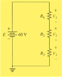
Chapter 5, Problem 37P
Find the voltage across each resistor in Fig. 5.123 if
Expert Solution & Answer
Want to see the full answer?
Check out a sample textbook solution
Students have asked these similar questions
Need handwritten solution not using chatgpt
Handwritten Solution please
The E-field pattern of an antenna. independent of , varies as follows:
E
0
0° ≤ 0≤ 45°
45°<≤
90°
90° <8180°
(a) What is the directivity of this antenna?
Umax
7
why did we use this law
Umax = 12 but we divided by 2?
In the sent Solution
=
R
27
Chapter 5 Solutions
Introductory Circuit Analysis (13th Edition)
Ch. 5 - For each configuration in Fig. 5.88, find the...Ch. 5 - For each configuration in Fig. 5.89, find the...Ch. 5 - Find the total resistance RT for each...Ch. 5 - Find the total resistance RT for each...Ch. 5 - For each circuit board in Fig. 5.92, �nd the...Ch. 5 - For the circuit in Fig. 5.93, composed of standard...Ch. 5 - For each configuration in Fig. 5.94, determine the...Ch. 5 - Find the resistance R, given the ohmmeter reading...Ch. 5 - What is the ohmmeter reading for each...Ch. 5 - For the series configuration in Fig. 5.97,...
Ch. 5 - For the series configuration in Fig. 5.98,...Ch. 5 - Find the applied voltage necessary to develop the...Ch. 5 - For each network in Fig. 5.100, constructed of...Ch. 5 - For each configuration in Fig. 5.101, what are the...Ch. 5 - For each configuration of Fig. 5.102, find the...Ch. 5 - For the circuit in Fig. 5.103, constructed of...Ch. 5 - Find the unknown quantities for the circuit of...Ch. 5 - Find the unknown quantities for the circuit in...Ch. 5 - Eight holiday lights are connected in series as...Ch. 5 - For the conditions specified in Fig. 5.107,...Ch. 5 - Combine the series voltage sources in Fig. 5.108,...Ch. 5 - Determine the current I and its direction for each...Ch. 5 - Find {he unknown voltage source and resistor for...Ch. 5 - Using Kirchhoffs voltage law, find the unknown...Ch. 5 - Find the current I for the network of Fig. 5.112....Ch. 5 - Using Kirchhoffs voltage law, determine the...Ch. 5 - Using Kirchhoffs voltage law, find the unknown...Ch. 5 - Determine the values of the unknown resistors in...Ch. 5 - For the configuration in Fig. 5.116, with standard...Ch. 5 - Using the voltage divider rule, find the indicated...Ch. 5 - Using the voltage divider rule or Kirchhoffs...Ch. 5 - Using the voltage divider rule or Kirchhoffs...Ch. 5 - Using the information provided, find the unknown...Ch. 5 - Using the voltage divider rule, �nd the unknown...Ch. 5 - Design a voltage divider circuit that will permit...Ch. 5 - Design the voltage divider in Fig. 5.122 such that...Ch. 5 - Find the voltage across each resistor in Fig....Ch. 5 - Design the circuit in Fig. 5.124 such that...Ch. 5 - Determine the voltages Va,Vb, and Vab for the...Ch. 5 - Determine the current I (with direction) and the...Ch. 5 - For the network in Fig. 5.127 determine the...Ch. 5 - Given the information appearing in Fig. 5.128,...Ch. 5 - Determine the values of R1,R2,R3, and R4 for the...Ch. 5 - For the network in Fig. 5.130, determine the...Ch. 5 - For the integrated circuit in Fig. 5.131,...Ch. 5 - For the integrated circuit in Fig. 5.132,...Ch. 5 - Find the internal resistance of a battery that has...Ch. 5 - Find the voltage to the load (full-and conditions)...Ch. 5 - Determine the current through the circuit in Fig....Ch. 5 - Use the computer to verify the results of Example...Ch. 5 - Use the computer to verify the results of Example...Ch. 5 - Use the computer to verify the results of Example...
Knowledge Booster


Learn more about
Need a deep-dive on the concept behind this application? Look no further. Learn more about this topic, electrical-engineering and related others by exploring similar questions and additional content below.Similar questions
- The normalized far-zone field pattern of an antenna is given by (sin cos²) E = 0 00 and 0 ≤ ≤ π/2. 3/22 π elsewhere Find the directivity using (a) the exact expression In the sent soalation Use Prad=2+1 7/2 Pre= 2 + 1 Sco³odo + 5 siño de Where did the 2 Com from?arrow_forwardPen and paper solution please with explaination not using chatgptarrow_forwardhowarrow_forward
- A four pole generator having wave wound armature winding has 51 slots ,each slot containing 20 conductors,what will be the voltage generated in the machine when driven at 1500rpm assuming the flux per pole is 7mWb Don't use Artificial intelligencearrow_forwardNeed Handwritten solution Do not use chatgpt Or AIarrow_forwardI need a detailed solution to a problem. The far-zone electric field intensity (array factor) of an end-fire two-element array antenna, placed along the z-axis and radiating into free-space, is given by E=cos (cos - 1) Find the directivity using (a) Kraus' approximate formula (b) the DIRECTIVITY computer program at the end of this chapter Repeat Problem 2.19 when E = cos -jkr 0505π $[ (cos + 1) (a). Elmax = Cost (case-1)] | max" = 1 at 8-0°. 0.707 Emax = 0.707.(1) = cos [(cose,-1)] (cose-1) = ± 0,= {Cos' (2) = does not exist (105(0)= 90° = rad. Bir Do≈ 4T ar=2() = = Bar 4-1-273 = 1.049 dB T₂ a. Elmax = cos((cose +1)), 0.707 = cos (Close,+1)) = 1 at 6 = π Imax (Cose+1)=== G₁ = cos(-2) does not exist. Girar=2()=π. 4T \cos (0) + 90° + rad Do≈ = +=1.273=1.049dB IT 2arrow_forward
- I need an expert mathematical solution. The E-field pattern of an antenna. independent of , varies as follows: 0° ≤ 0≤ 45° E = 0 45° {1 90° 90° < 0 ≤ 180° (a) What is the directivity of this antenna? (b) What is the radiation resistance of the antenna at 200 m from it if the field is equal to 10 V/m (rms) for Ø = 0° at that distance and the terminal current is 5 A (rms)?arrow_forwardI need an expert mathematical solution. The normalized far-zone field pattern of an antenna is given by E = {® (sin cos)/ 0 Find the directivity using 0 ≤ 0 ≤ π and 0≤ 0≤ π/2. 3m2sds2, elsewherearrow_forwardI need an expert mathematical solution. The radiation intensity of an aperture antenna, mounted on an infinite ground plane with perpendicular to the aperture. is rotationally symmetric (not a function of 4), and it is given by sin (7 sin 0) U π sin Find the approximate directivity (dimensionless and in dB) usingarrow_forward
- Waveforms v1(t) and v2(t) are given by:v1(t) = −4 sin(6π ×10^4t +30◦) V,v2(t) = 2cos(6π ×10^4t −30◦) V.Does v2(t) lead or lag v1(t), and by what phase angle?arrow_forward7.1 Express the current waveform i(t) = -0.2 cos(6 × 10°1 +60°) mA in standard cosine form and then determine the following: (a) Its amplitude, frequency, and phase angle. (b) i(t) at t=0.1 ns.arrow_forward3. Consider the RC circuit with a constant voltage source shown in the diagram below. The values of the resistor, capacitor, and input voltage are R = 50, C = 10 µF, and V = 6V, respectively. Assume that there is initially no charge on the capacitor before the switch is closed. Vo ↑i(t) R w C When the switch closes at time t = 0, the current begins to flow as a function of time according to the equation i(t) = ioencarrow_forward
arrow_back_ios
SEE MORE QUESTIONS
arrow_forward_ios
Recommended textbooks for you
 Introductory Circuit Analysis (13th Edition)Electrical EngineeringISBN:9780133923605Author:Robert L. BoylestadPublisher:PEARSON
 Delmar's Standard Textbook Of ElectricityElectrical EngineeringISBN:9781337900348Author:Stephen L. HermanPublisher:Cengage Learning
 Programmable Logic ControllersElectrical EngineeringISBN:9780073373843Author:Frank D. PetruzellaPublisher:McGraw-Hill Education
 Fundamentals of Electric CircuitsElectrical EngineeringISBN:9780078028229Author:Charles K Alexander, Matthew SadikuPublisher:McGraw-Hill Education
 Electric Circuits. (11th Edition)Electrical EngineeringISBN:9780134746968Author:James W. Nilsson, Susan RiedelPublisher:PEARSON
 Engineering ElectromagneticsElectrical EngineeringISBN:9780078028151Author:Hayt, William H. (william Hart), Jr, BUCK, John A.Publisher:Mcgraw-hill Education,
Introductory Circuit Analysis (13th Edition)
Electrical Engineering
ISBN:9780133923605
Author:Robert L. Boylestad
Publisher:PEARSON
Delmar's Standard Textbook Of Electricity
Electrical Engineering
ISBN:9781337900348
Author:Stephen L. Herman
Publisher:Cengage Learning
Programmable Logic Controllers
Electrical Engineering
ISBN:9780073373843
Author:Frank D. Petruzella
Publisher:McGraw-Hill Education
Fundamentals of Electric Circuits
Electrical Engineering
ISBN:9780078028229
Author:Charles K Alexander, Matthew Sadiku
Publisher:McGraw-Hill Education
Electric Circuits. (11th Edition)
Electrical Engineering
ISBN:9780134746968
Author:James W. Nilsson, Susan Riedel
Publisher:PEARSON
Engineering Electromagnetics
Electrical Engineering
ISBN:9780078028151
Author:Hayt, William H. (william Hart), Jr, BUCK, John A.
Publisher:Mcgraw-hill Education,
Kirchhoff's Rules of Electrical Circuits; Author: Flipping Physics;https://www.youtube.com/watch?v=d0O-KUKP4nM;License: Standard YouTube License, CC-BY