
Introductory Circuit Analysis (13th Edition)
13th Edition
ISBN: 9780133923605
Author: Robert L. Boylestad
Publisher: PEARSON
expand_more
expand_more
format_list_bulleted
Concept explainers
Videos
Textbook Question
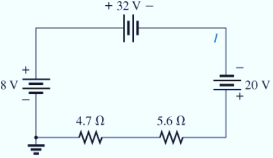
Chapter 5, Problem 22P
Determine the current I and its direction for each network in Fig. 5.109. Before solving for I, redraw each network with a single voltage source.
Expert Solution & Answer
Want to see the full answer?
Check out a sample textbook solution
Students have asked these similar questions
Don't use ai to answer I will report you answer
A plane wave traveling in z-direction through a medium with &=8, μ-2 and has
the electric and magnetic field intensity at z=0 shown in Fig. 6.1 and Fig. 6.2, respectively. Utilize the
provided information to find the following:
(a) w
(b) The intrinsic impedance of the medium
© B
(d) a
(e) The expression of the magnetic field intensity, H
(f) The time-average power carried by the wave
Magnetic Field Intensity (mA/m)
Electric Field Intensity (V/m)
0.5
0.4-
0.3
0.2
ཧཱུྃ༔ཤྲུསྦྱ ཌུ ཋ ; སྟྲི " ° ཝཱ
0.1
-0.5
Ex
-2.0
-1.5
-1.0
-0.5
0.0
0.5
1.0
1.5
Fig 6.2
Hy
2.0
Time (ns)².
-2.0
-1.5
-1.0
-0.5
0.0;
0.5
1.0
Time (ns)
2.0
0.083 ns or 0.0415 T
Don't use ai to answer I will report you answer
Chapter 5 Solutions
Introductory Circuit Analysis (13th Edition)
Ch. 5 - For each configuration in Fig. 5.88, find the...Ch. 5 - For each configuration in Fig. 5.89, find the...Ch. 5 - Find the total resistance RT for each...Ch. 5 - Find the total resistance RT for each...Ch. 5 - For each circuit board in Fig. 5.92, �nd the...Ch. 5 - For the circuit in Fig. 5.93, composed of standard...Ch. 5 - For each configuration in Fig. 5.94, determine the...Ch. 5 - Find the resistance R, given the ohmmeter reading...Ch. 5 - What is the ohmmeter reading for each...Ch. 5 - For the series configuration in Fig. 5.97,...
Ch. 5 - For the series configuration in Fig. 5.98,...Ch. 5 - Find the applied voltage necessary to develop the...Ch. 5 - For each network in Fig. 5.100, constructed of...Ch. 5 - For each configuration in Fig. 5.101, what are the...Ch. 5 - For each configuration of Fig. 5.102, find the...Ch. 5 - For the circuit in Fig. 5.103, constructed of...Ch. 5 - Find the unknown quantities for the circuit of...Ch. 5 - Find the unknown quantities for the circuit in...Ch. 5 - Eight holiday lights are connected in series as...Ch. 5 - For the conditions specified in Fig. 5.107,...Ch. 5 - Combine the series voltage sources in Fig. 5.108,...Ch. 5 - Determine the current I and its direction for each...Ch. 5 - Find {he unknown voltage source and resistor for...Ch. 5 - Using Kirchhoffs voltage law, find the unknown...Ch. 5 - Find the current I for the network of Fig. 5.112....Ch. 5 - Using Kirchhoffs voltage law, determine the...Ch. 5 - Using Kirchhoffs voltage law, find the unknown...Ch. 5 - Determine the values of the unknown resistors in...Ch. 5 - For the configuration in Fig. 5.116, with standard...Ch. 5 - Using the voltage divider rule, find the indicated...Ch. 5 - Using the voltage divider rule or Kirchhoffs...Ch. 5 - Using the voltage divider rule or Kirchhoffs...Ch. 5 - Using the information provided, find the unknown...Ch. 5 - Using the voltage divider rule, �nd the unknown...Ch. 5 - Design a voltage divider circuit that will permit...Ch. 5 - Design the voltage divider in Fig. 5.122 such that...Ch. 5 - Find the voltage across each resistor in Fig....Ch. 5 - Design the circuit in Fig. 5.124 such that...Ch. 5 - Determine the voltages Va,Vb, and Vab for the...Ch. 5 - Determine the current I (with direction) and the...Ch. 5 - For the network in Fig. 5.127 determine the...Ch. 5 - Given the information appearing in Fig. 5.128,...Ch. 5 - Determine the values of R1,R2,R3, and R4 for the...Ch. 5 - For the network in Fig. 5.130, determine the...Ch. 5 - For the integrated circuit in Fig. 5.131,...Ch. 5 - For the integrated circuit in Fig. 5.132,...Ch. 5 - Find the internal resistance of a battery that has...Ch. 5 - Find the voltage to the load (full-and conditions)...Ch. 5 - Determine the current through the circuit in Fig....Ch. 5 - Use the computer to verify the results of Example...Ch. 5 - Use the computer to verify the results of Example...Ch. 5 - Use the computer to verify the results of Example...
Additional Engineering Textbook Solutions
Find more solutions based on key concepts
CONCEPT QUESTIONS
15.CQ3 The ball rolls without slipping on the fixed surface as shown. What is the direction ...
Vector Mechanics for Engineers: Statics and Dynamics
This optional Google account security feature sends you a message with a code that you must enter, in addition ...
SURVEY OF OPERATING SYSTEMS
Assume a telephone signal travels through a cable at two-thirds the speed of light. How long does it take the s...
Electric Circuits. (11th Edition)
What are the design issues for character string types?
Concepts Of Programming Languages
What is an uninitialized variable?
Starting Out with Programming Logic and Design (5th Edition) (What's New in Computer Science)
17–1C A high-speed aircraft is cruising in still air. How does the temperature of air at the nose of the aircra...
Thermodynamics: An Engineering Approach
Knowledge Booster


Learn more about
Need a deep-dive on the concept behind this application? Look no further. Learn more about this topic, electrical-engineering and related others by exploring similar questions and additional content below.Similar questions
- Please help mearrow_forward3.7 The AM signal s(t) = Ac[1+kam(t)] cos(2nfct) is applied to the system shown in Figure P3.7. Assuming that |kam(t) 2W, show that m(t) can be obtained from the square-rooter output U3(t). s(t) Squarer v1(t) Low-pass 12(t) Square- filter ra(t) rooter V₁ (t) = 5² (t) 13(1)=√√12 (1) Figure P3.7arrow_forwardPlease help mearrow_forward
- Please help mearrow_forwardCan you check my connections and answers.arrow_forwardA communication satellite is in stationary (synchronous) orbit about the earch (assume altitude of 22.300 statute miles). Its transmitter generates 8.00 W. Assume the transmit- ting antenna is isotropic. Its signal is received by the 210-ft diameter tracking parabo- loidal antenna on the earth at the NASA tracking station at Goldstone, California. Also assume no resistive loss in either antenna, perfect polarization match, and perfect impedance match at both antennas. At a frequency of 2 GHz, determine the: (a) power density (in watts/m²) incident on the receiving antenna. (b) power received by the ground-based antenna whose gain is 60 dB.arrow_forward
- Determine VO during the Negative Half Cycle of the input voltage, Vi 12 V f = 1 kHz -12 V C ... + 0.1 με Si R 56 ΚΩ Vo Vi 2 V - 0 +arrow_forward50mV and 10kHz from the function generator to the input. The mulitmeter postive is connected to the output and negative to a ground. Is the circuit connected correctly? Yes or No. Does the reading look correct? I don't need calculations but will take them. I just need to know if the connection is right. Connect a signal generator to the input and set it for 50 mV Sine wave with a frequency of 10 kHz. Connect the output to a multimeter set to RMS voltage. Record the output voltage and frequency in the following table. Repeat the measurement for all given frequency values in the table.arrow_forwardThe input reactance of an infinitesimal linear dipole of length A/60 and radius a=A/200 is given by Xin = – 120 [In(€/a) — 1] tan(ke) Assuming the wire of the dipole is copper with a conductivity of 5.7 x 10' S/m, determine at f = 1 GHz the (a) loss resistance (b) radiation resistance (c) radiation efficiency (d) VSWR when the antenna is connected to a 50-ohm linearrow_forward
arrow_back_ios
SEE MORE QUESTIONS
arrow_forward_ios
Recommended textbooks for you
 Delmar's Standard Textbook Of ElectricityElectrical EngineeringISBN:9781337900348Author:Stephen L. HermanPublisher:Cengage Learning
Delmar's Standard Textbook Of Electricity
Electrical Engineering
ISBN:9781337900348
Author:Stephen L. Herman
Publisher:Cengage Learning
Kirchhoff's Rules of Electrical Circuits; Author: Flipping Physics;https://www.youtube.com/watch?v=d0O-KUKP4nM;License: Standard YouTube License, CC-BY