
Introductory Circuit Analysis (13th Edition)
13th Edition
ISBN: 9780133923605
Author: Robert L. Boylestad
Publisher: PEARSON
expand_more
expand_more
format_list_bulleted
Concept explainers
Videos
Textbook Question
Chapter 5, Problem 11P
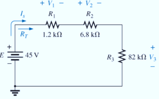
For the series configuration in Fig. 5.98, constructed using standard value resistors:
- Without making a single calculation, which resistive element will have the most voltage across it? Which will have the least?
- Which resistor will have the most impact on the total resistance and the resulting current? Find the total resistance and the current.
- Find the voltage across each element and review your response to part (a).
Expert Solution & Answer
Want to see the full answer?
Check out a sample textbook solution
Students have asked these similar questions
c)
An RC circuit is given in Figure Q1.1, where Vi(t) and Vo(t) are the input and
output voltages.
(i) Derive the transfer function of the circuit.
(ii) With a unit step change of Vi(t) applied to the circuit, derive the time
response of Vo(t) with this step change.
Vi(t)
C₁
Vo(1)
R₂ C2 C3 |
R = 20 ΚΩ = 50 ΚΩ
C=C2=C3=25 μF
Figure Q1.1. RC circuit.
c) An RC circuit is given in Figure Q1. vi(t) and vo (t) are the input and output
voltages.
(i) Derive the transfer function of the circuit.
(ii) With a unit step change vi(t) applied to the circuit, derive and sketch the
time response of the circuit.
R₁ R2
v₁(t)
R3 C₁
v₁(t)
R₁ = R₂ = 10 k
R3
= 100 kn C₁ = 100 μF
Figure Q1. RC circuit.
c)
A RC circuit is given in Figure Q1.1. Vi(t) and Vo(t) are the input and output
voltages.
(i) Derive the transfer function of the circuit.
(ii)
With a unit step change of Vi(t) applied to the circuit, derive the time
response of the circuit.
C₁ C₂
Vi(t)
Vo(1)
R₁ C₂
R-25 k C=C2=50 µF
Figure Q1.1. RC circuit.
Chapter 5 Solutions
Introductory Circuit Analysis (13th Edition)
Ch. 5 - For each configuration in Fig. 5.88, find the...Ch. 5 - For each configuration in Fig. 5.89, find the...Ch. 5 - Find the total resistance RT for each...Ch. 5 - Find the total resistance RT for each...Ch. 5 - For each circuit board in Fig. 5.92, �nd the...Ch. 5 - For the circuit in Fig. 5.93, composed of standard...Ch. 5 - For each configuration in Fig. 5.94, determine the...Ch. 5 - Find the resistance R, given the ohmmeter reading...Ch. 5 - What is the ohmmeter reading for each...Ch. 5 - For the series configuration in Fig. 5.97,...
Ch. 5 - For the series configuration in Fig. 5.98,...Ch. 5 - Find the applied voltage necessary to develop the...Ch. 5 - For each network in Fig. 5.100, constructed of...Ch. 5 - For each configuration in Fig. 5.101, what are the...Ch. 5 - For each configuration of Fig. 5.102, find the...Ch. 5 - For the circuit in Fig. 5.103, constructed of...Ch. 5 - Find the unknown quantities for the circuit of...Ch. 5 - Find the unknown quantities for the circuit in...Ch. 5 - Eight holiday lights are connected in series as...Ch. 5 - For the conditions specified in Fig. 5.107,...Ch. 5 - Combine the series voltage sources in Fig. 5.108,...Ch. 5 - Determine the current I and its direction for each...Ch. 5 - Find {he unknown voltage source and resistor for...Ch. 5 - Using Kirchhoffs voltage law, find the unknown...Ch. 5 - Find the current I for the network of Fig. 5.112....Ch. 5 - Using Kirchhoffs voltage law, determine the...Ch. 5 - Using Kirchhoffs voltage law, find the unknown...Ch. 5 - Determine the values of the unknown resistors in...Ch. 5 - For the configuration in Fig. 5.116, with standard...Ch. 5 - Using the voltage divider rule, find the indicated...Ch. 5 - Using the voltage divider rule or Kirchhoffs...Ch. 5 - Using the voltage divider rule or Kirchhoffs...Ch. 5 - Using the information provided, find the unknown...Ch. 5 - Using the voltage divider rule, �nd the unknown...Ch. 5 - Design a voltage divider circuit that will permit...Ch. 5 - Design the voltage divider in Fig. 5.122 such that...Ch. 5 - Find the voltage across each resistor in Fig....Ch. 5 - Design the circuit in Fig. 5.124 such that...Ch. 5 - Determine the voltages Va,Vb, and Vab for the...Ch. 5 - Determine the current I (with direction) and the...Ch. 5 - For the network in Fig. 5.127 determine the...Ch. 5 - Given the information appearing in Fig. 5.128,...Ch. 5 - Determine the values of R1,R2,R3, and R4 for the...Ch. 5 - For the network in Fig. 5.130, determine the...Ch. 5 - For the integrated circuit in Fig. 5.131,...Ch. 5 - For the integrated circuit in Fig. 5.132,...Ch. 5 - Find the internal resistance of a battery that has...Ch. 5 - Find the voltage to the load (full-and conditions)...Ch. 5 - Determine the current through the circuit in Fig....Ch. 5 - Use the computer to verify the results of Example...Ch. 5 - Use the computer to verify the results of Example...Ch. 5 - Use the computer to verify the results of Example...
Additional Engineering Textbook Solutions
Find more solutions based on key concepts
How is the hydrodynamic entry length defined for flow in a pipe? Is the entry length longer in laminar or turbu...
Fluid Mechanics: Fundamentals and Applications
How are relationships between tables expressed in a relational database?
Modern Database Management
Porter’s competitive forces model: The model is used to provide a general view about the firms, the competitors...
Management Information Systems: Managing The Digital Firm (16th Edition)
The solid steel shaft AC has a diameter of 25 mm and is supported by smooth bearings at D and E. It is coupled ...
Mechanics of Materials (10th Edition)
What types of coolant are used in vehicles?
Automotive Technology: Principles, Diagnosis, And Service (6th Edition) (halderman Automotive Series)
A byte is made up of eight a. CPUs b. addresses c. variables d. bits
Starting Out with Java: From Control Structures through Objects (7th Edition) (What's New in Computer Science)
Knowledge Booster


Learn more about
Need a deep-dive on the concept behind this application? Look no further. Learn more about this topic, electrical-engineering and related others by exploring similar questions and additional content below.Similar questions
- Answer 2 questions for 100 marks Question 1: Process Design [25 marks] An incomplete process design of a flash drum distillation unit is presented in Figure 1. The key variables to be controlled are flow rate, temperature, composition, pressure and liquid level in the drum. Disturbances are observed in the feed temperature and composition. Heat exchangers Drum Vapor Liquid Pump Figure 1: Incomplete process design of a distillation unit Answer the following questions briefly and in a qualitative fashion: a) Determine which sensors and final elements are required so that the important variables can be controlled. Sketch them in the figure using correct instrumentation tags. Describe briefly what instruments you will use and where they should be located. Reflect on the potential presence of a flow controller upstream of your process design (not shown in the diagram). How would this affect the level controller in the drum? b) [10 marks] Describe briefly how you qualitatively determine the…arrow_forwardAnswer 2 questions for 100 marks Question 1: Process Design [25 marks] An incomplete process design of a flash drum distillation unit is presented in Figure 1. The key variables to be controlled are flow rate, temperature, composition, pressure and liquid level in the drum. Disturbances are observed in the feed temperature and composition. Heat exchangers Drum Vapor Liquid Pump Figure 1: Incomplete process design of a distillation unit Answer the following questions briefly and in a qualitative fashion: a) Determine which sensors and final elements are required so that the important variables can be controlled. Sketch them in the figure using correct instrumentation tags. Describe briefly what instruments you will use and where they should be located. Reflect on the potential presence of a flow controller upstream of your process design (not shown in the diagram). How would this affect the level controller in the drum? b) [10 marks] Describe briefly how you qualitatively determine the…arrow_forwardQuestion 2: Process Control [75 marks] As a process engineer, you are tasked to control the process shown in Figure 2. For biomedical engineers, the process could be interpreted as the injection of a solution of a medication compound A, with initial concentration CAO, into a human body, simplified as a Continuously Stirred Tank Reactor (CSTR). Therefore, your task is to analyse and model this process. The equipment consists of a mixing tank, mixing pipe and CSTR. F₁ Сло CA2 V₁ mixing pipe F4 CA4 F3 CA3 mixing tank Fs CAS Vs stirred-tank reactor Figure 2: Mixing and reaction processes Assumptions used for modelling are as follows: I. Both tanks are well mixed and have constant volume and temperature. II. All pipes are short and contribute negligible transportation delay, III. All flow rates are constant. All densities are constant and uniform throughout. IV. The first tank is a mixing tank. V. VI. The mixing pipe has no accumulation, and the concentration CA3 is constant The second tank…arrow_forward
- a) Reflect on the assumptions and briefly explain their implications for your model. Do you agree with the assumptions? If not, briefly suggest improved assumptions. [6 marks] b) Derive a linear(ised) model (algebraic or differential equation) relating C'A2(t) to C'Ao(f). How do you define your system? What type of balance do you need to solve for this purpose? [12 marks] c) Derive a linear(ised) model (algebraic or differential equation) relating C'A4(t) to C'A2(f). Show your balance equation. [12 marks] d) Derive a linear(ised) model (algebraic or differential equation) relating C'A5(t) to C'A4(f). Show your balance equation. [12 marks] e) Combine the models in parts (a) to (c) into one equation relating C'A5 to C'Ao using Laplace transforms. [15 marks] f) Is the response (for example to step input) stable or unstable? Is the response periodic? Is the response damped? [6 marks] g) Carry out an inverse Laplace Transform for C'Ao(s) = A CAO/s (step function) to find C'A5(t) in the time…arrow_forwardI need helparrow_forwardThe values of the circuit elements in the circuit shown in the figure are given below.The initial energies of the capacitors and the coil are zero.Accordingly, how many volts is the voltage vo at t=0.55 seconds? vs(t) = 2cos(4000t)u(t) VR = 19 ohmL = 20 HC1 = 1/5 FC2 = 1/2 Farrow_forward
- could you please show steps on how the answer was derived. Vo(t)=3.922 cos(1000t-71.31')Varrow_forwardcan you show the steps to answer question.arrow_forwardQ2. Figure Q2 shows a block diagram with an input of C(s) and an output R(s). a) C(s) K₁ R(s) K2 1 + 5s 1+2s Figure Q2. Block diagram of control system. Simply the block diagram to get the transfer function of the system C(s)/R(s). b) What is the order of the system? c) What is the gain of the system? d) Determine the values of K₁ and K₂ to obtain a natural frequency w of 0.5 rad/s and damping ratio of 0.4. e) What is the rise time and overshoot of the system with a unit step input?arrow_forward
- Q4. a) A purely derivative controller (i.e. with a zero at the origin only) is defined by an improper transfer function. Considering its asymptotic behaviour, explain why a purely derivative controller is difficult to implement in practice. Relate your explanation to the potential limitations on system performance. b) Discuss the potential issues faced by a control system with a large cut-off frequency. Relate your discussion to the implications on system performance. c) The transfer function of a lag compensator is given by 2 KPID(S) = 2.2++0.2s S By using the asymptotic approximation technique: (i) Obtain the standard form and corner frequency for each individual component of KPID(S). (ii) Clearly describe the asymptotic behaviour of each individual component of KPID(S).arrow_forwardModule Code: EN2058 Q1. a) List the advantages and disadvantages of a closed loop system compared to an open loop system. b) c) What is the procedure for designing a control system for a bread toaster? An RC circuit is given in Figure Q1. vi(t) and v(t) are the input and output voltages. (i) Derive the transfer function of the circuit. (ii) With a unit step change vi(t) applied to the circuit, derive and sketch the time response of the circuit. R1 R2 v₁(t) R3 C1 vo(t) R₁ =R2 = 10 k R3 = 100 kn C₁ = 100 μF Figure Q1. RC circuit. (iii) Assuming zero initial conditions, obtain the impulse and ramp responses of the circuit from the step response derived in (ii). Sketching is not needed.arrow_forwardQ3. a) The frequency response method enables the study of the steady-state response of a system G(s). What type of inputs are used for frequency response? If the system is linear and stable, how does the output differ from the input? Compare the main characteristics of two types frequency response plots. b) Consider the control system shown in Figure Q3. Controller E(s) R(s) Desired output C(s) Plant G(s) Y(s) Actual output 3(s + 3) C(s) = k G(s) = = s(s - 1)(s + 10) Figure Q3. Closed-loop system. (i) Considering definitions in the study of bounded-input bounded-output stability, is G(s) stable? Classify the poles and zeros of G(s). (ii) G(s) defined in Figure Q3 is a system completely characterised by its transfer function. Explain why this is the case. (iii) Obtain the closed-loop transfer function P(s) = Y(s)/R(s) of the system. (iv) Based on your result for the previous question [Question 3b)-(iii)], use the Routh-Hurwitz stability criterion to determine suitable values of gain K…arrow_forward
arrow_back_ios
SEE MORE QUESTIONS
arrow_forward_ios
Recommended textbooks for you
 EBK ELECTRICAL WIRING RESIDENTIALElectrical EngineeringISBN:9781337516549Author:SimmonsPublisher:CENGAGE LEARNING - CONSIGNMENT
 Delmar's Standard Textbook Of ElectricityElectrical EngineeringISBN:9781337900348Author:Stephen L. HermanPublisher:Cengage Learning
EBK ELECTRICAL WIRING RESIDENTIAL
Electrical Engineering
ISBN:9781337516549
Author:Simmons
Publisher:CENGAGE LEARNING - CONSIGNMENT
Delmar's Standard Textbook Of Electricity
Electrical Engineering
ISBN:9781337900348
Author:Stephen L. Herman
Publisher:Cengage Learning
Kirchhoff's Rules of Electrical Circuits; Author: Flipping Physics;https://www.youtube.com/watch?v=d0O-KUKP4nM;License: Standard YouTube License, CC-BY