
Introductory Circuit Analysis (13th Edition)
13th Edition
ISBN: 9780133923605
Author: Robert L. Boylestad
Publisher: PEARSON
expand_more
expand_more
format_list_bulleted
Concept explainers
Videos
Textbook Question
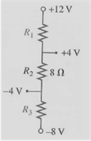
Chapter 5, Problem 42P
Given the information appearing in Fig. 5.128, find the level of resistance for
Expert Solution & Answer

Trending nowThis is a popular solution!

Students have asked these similar questions
A half-wave controlled rectifier is supplied by a 230 Vrms voltage source and has load resistance of
2502. Calculate the delay angle a that produces a load-absorbed power of 200W.
not use ai please
Figure 1 shows a half-wave controlled rectifier which is supplied by a Vin = 120 Vrms voltage
source. Assume that the load resistance is R = 10 2. Determine:
a) The firing angle a of the thyristor to
produce an average output voltage 50Vdc.
Vin=Vmsinoot
b) The average power Po absorbed by the load R.
Figure 1
R = 1092
Chapter 5 Solutions
Introductory Circuit Analysis (13th Edition)
Ch. 5 - For each configuration in Fig. 5.88, find the...Ch. 5 - For each configuration in Fig. 5.89, find the...Ch. 5 - Find the total resistance RT for each...Ch. 5 - Find the total resistance RT for each...Ch. 5 - For each circuit board in Fig. 5.92, �nd the...Ch. 5 - For the circuit in Fig. 5.93, composed of standard...Ch. 5 - For each configuration in Fig. 5.94, determine the...Ch. 5 - Find the resistance R, given the ohmmeter reading...Ch. 5 - What is the ohmmeter reading for each...Ch. 5 - For the series configuration in Fig. 5.97,...
Ch. 5 - For the series configuration in Fig. 5.98,...Ch. 5 - Find the applied voltage necessary to develop the...Ch. 5 - For each network in Fig. 5.100, constructed of...Ch. 5 - For each configuration in Fig. 5.101, what are the...Ch. 5 - For each configuration of Fig. 5.102, find the...Ch. 5 - For the circuit in Fig. 5.103, constructed of...Ch. 5 - Find the unknown quantities for the circuit of...Ch. 5 - Find the unknown quantities for the circuit in...Ch. 5 - Eight holiday lights are connected in series as...Ch. 5 - For the conditions specified in Fig. 5.107,...Ch. 5 - Combine the series voltage sources in Fig. 5.108,...Ch. 5 - Determine the current I and its direction for each...Ch. 5 - Find {he unknown voltage source and resistor for...Ch. 5 - Using Kirchhoffs voltage law, find the unknown...Ch. 5 - Find the current I for the network of Fig. 5.112....Ch. 5 - Using Kirchhoffs voltage law, determine the...Ch. 5 - Using Kirchhoffs voltage law, find the unknown...Ch. 5 - Determine the values of the unknown resistors in...Ch. 5 - For the configuration in Fig. 5.116, with standard...Ch. 5 - Using the voltage divider rule, find the indicated...Ch. 5 - Using the voltage divider rule or Kirchhoffs...Ch. 5 - Using the voltage divider rule or Kirchhoffs...Ch. 5 - Using the information provided, find the unknown...Ch. 5 - Using the voltage divider rule, �nd the unknown...Ch. 5 - Design a voltage divider circuit that will permit...Ch. 5 - Design the voltage divider in Fig. 5.122 such that...Ch. 5 - Find the voltage across each resistor in Fig....Ch. 5 - Design the circuit in Fig. 5.124 such that...Ch. 5 - Determine the voltages Va,Vb, and Vab for the...Ch. 5 - Determine the current I (with direction) and the...Ch. 5 - For the network in Fig. 5.127 determine the...Ch. 5 - Given the information appearing in Fig. 5.128,...Ch. 5 - Determine the values of R1,R2,R3, and R4 for the...Ch. 5 - For the network in Fig. 5.130, determine the...Ch. 5 - For the integrated circuit in Fig. 5.131,...Ch. 5 - For the integrated circuit in Fig. 5.132,...Ch. 5 - Find the internal resistance of a battery that has...Ch. 5 - Find the voltage to the load (full-and conditions)...Ch. 5 - Determine the current through the circuit in Fig....Ch. 5 - Use the computer to verify the results of Example...Ch. 5 - Use the computer to verify the results of Example...Ch. 5 - Use the computer to verify the results of Example...
Additional Engineering Textbook Solutions
Find more solutions based on key concepts
What is the importance of modeling in engineering? How are the mathematical models for engineering processes pr...
HEAT+MASS TRANSFER:FUND.+APPL.
Porter’s competitive forces model: The model is used to provide a general view about the firms, the competitors...
Management Information Systems: Managing The Digital Firm (16th Edition)
The following C++ program will not compile because the lines have been mixed up. cout Success\n; cout Success...
Starting Out with C++ from Control Structures to Objects (9th Edition)
How are relationships between tables expressed in a relational database?
Modern Database Management
Locate the centroid of the area. Prob. 9-17
INTERNATIONAL EDITION---Engineering Mechanics: Statics, 14th edition (SI unit)
What types of coolant are used in vehicles?
Automotive Technology: Principles, Diagnosis, And Service (6th Edition) (halderman Automotive Series)
Knowledge Booster


Learn more about
Need a deep-dive on the concept behind this application? Look no further. Learn more about this topic, electrical-engineering and related others by exploring similar questions and additional content below.Similar questions
- Q1. What is power dissipation in the Zener diode circuit given for a) RL=100 Ohm ? b) RL=∞arrow_forwardThe one-line diagram of an unloaded power system is shown below. Reactances of the two sections of transmission line are shown on the diagram. The generators and transformers are rated as follows: 20 MVA, 13.8 kV, X = 0.20 p.u Generator 1: Generator 2: Generator 3: 30 MVA, 18 kV, X = 0.20 p.u Transformer Ti: Transformer T2: 30 MVA, 20 kV, X = 0.20 p.u 25 MVA, 220Y/13.8A kV, X = 10% Three single-phase units each rated 10 MVA, 127/18 kV, X = 10% HT sides connected in wye Transformer T3: LT sides connected in delta 35 MVA, 220Y/22Y KV, X = 10% j80 Q j100 Q Line 1 Line 2 T₁ T₂ Draw the impedance diagram with all reactances marked in per unit. Choose a base of 50 MVA, 13.8 kV in the circuit of generator 1.arrow_forwardntotnarrow_forward
- In Fig.35 resistive loads, 1, 2, and 3, respectively, absorb 1200 W, 2400 W, and 3600 W. Calculate the current: a. In lines A and B. b. In the neutral conductors. c. In the HV line.arrow_forward+ -ww I 2 12V 2 Determine I, I,, I₂ and V₁ 1 _< + www 5 12 16 6 5 wwwarrow_forwardDetermine (a) the average and (b) rms values of the periodiccurrent waveform shown in Fig. P8.9arrow_forward
- Repairs have to be carried out on HV cir- cuit breaker No. 6 shown in Fig. 26. If the three 220 kV lines must be kept in service, which disconnecting switches must be kept open?arrow_forwardFind the voltage v(t) for t>=0 show all steps and redraw circuit as necessary, the switch closes at t=0 and v(t) is the voltage over the 4ohm resistor as shown in the circuit.arrow_forwardFind the voltage v(t) for t>=0 please redraw circuit as necessary and show all steps.arrow_forward
- Determine (a) the average and (b) rms values of the periodiccurrent waveform shown in Fig. P8.9arrow_forwardFind Eigenvalues and Eigenvectors for the following matrices: [5 -6 1 A = 1 1 0 3 0 1arrow_forwardUse Gauss-Jordan Elimination method to solve the following system: 4x1+5x2 + x3 = 2 x1-2x2-3x3 = 7 3x1 x2 2x3 = 1. -arrow_forward
arrow_back_ios
SEE MORE QUESTIONS
arrow_forward_ios
Recommended textbooks for you
 Introductory Circuit Analysis (13th Edition)Electrical EngineeringISBN:9780133923605Author:Robert L. BoylestadPublisher:PEARSON
 Delmar's Standard Textbook Of ElectricityElectrical EngineeringISBN:9781337900348Author:Stephen L. HermanPublisher:Cengage Learning
 Programmable Logic ControllersElectrical EngineeringISBN:9780073373843Author:Frank D. PetruzellaPublisher:McGraw-Hill Education
 Fundamentals of Electric CircuitsElectrical EngineeringISBN:9780078028229Author:Charles K Alexander, Matthew SadikuPublisher:McGraw-Hill Education
 Electric Circuits. (11th Edition)Electrical EngineeringISBN:9780134746968Author:James W. Nilsson, Susan RiedelPublisher:PEARSON
 Engineering ElectromagneticsElectrical EngineeringISBN:9780078028151Author:Hayt, William H. (william Hart), Jr, BUCK, John A.Publisher:Mcgraw-hill Education,
Introductory Circuit Analysis (13th Edition)
Electrical Engineering
ISBN:9780133923605
Author:Robert L. Boylestad
Publisher:PEARSON
Delmar's Standard Textbook Of Electricity
Electrical Engineering
ISBN:9781337900348
Author:Stephen L. Herman
Publisher:Cengage Learning
Programmable Logic Controllers
Electrical Engineering
ISBN:9780073373843
Author:Frank D. Petruzella
Publisher:McGraw-Hill Education
Fundamentals of Electric Circuits
Electrical Engineering
ISBN:9780078028229
Author:Charles K Alexander, Matthew Sadiku
Publisher:McGraw-Hill Education
Electric Circuits. (11th Edition)
Electrical Engineering
ISBN:9780134746968
Author:James W. Nilsson, Susan Riedel
Publisher:PEARSON
Engineering Electromagnetics
Electrical Engineering
ISBN:9780078028151
Author:Hayt, William H. (william Hart), Jr, BUCK, John A.
Publisher:Mcgraw-hill Education,
Kirchhoff's Rules of Electrical Circuits; Author: Flipping Physics;https://www.youtube.com/watch?v=d0O-KUKP4nM;License: Standard YouTube License, CC-BY