
Introductory Circuit Analysis (13th Edition)
13th Edition
ISBN: 9780133923605
Author: Robert L. Boylestad
Publisher: PEARSON
expand_more
expand_more
format_list_bulleted
Concept explainers
Videos
Textbook Question
thumb_up100%
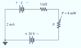
Chapter 5, Problem 23P
Find {he unknown voltage source and resistor for the networks in Fig. 5.110. First combine the series voltage sources into a single source. Indicate the direction of the resulting current.
Expert Solution & Answer

Learn your wayIncludes step-by-step video

schedule08:39
Students have asked these similar questions
1) In the Fig. 5 – 4, between points A and B, which branch of the circuit has the greatest current flow if all resistors have the exact values indicated?a. R2, R3.b. R4c. R5d. All branch currents are the same value.
2) Which of the following would be a true statement if resistor R7 became short circuited in Fig. 5 – 4.a. Current flow would decrease.b. Voltage E AB would decrease.c. Voltage E CD would increase.d. Current flow would increase.
6. Which of the following would be a false statement if resistor R7 opened in Fig. 5 – 4?a. Current flow would decrease.b. Voltage E AB would decrease.c. Voltage E CD would increase.d. None of the above.
Problem 5.1: Calculate the voltage at V relative to ground in the following circuit. Assume the following values: V1 = 12 V, V2 = 10 V, R₁ =4 kQ, R2 = 2 kQ, and R3 = 3 kQ,.
Give your answer in units of volts.
V2
R₁
V
+1
V₁
Ry
w
R2
Question 5: For the two circuit given below,
a. Find the total resistance, RT, and solve for the current, I, through the voltage source.
b. Find all of the unknown currents in the circuit.
c. Verify Kirchhoff's current law at node a.
d. Determine the power dissipated by each resistor. Verify that the total power dissipated
by the resistors is equal to the power delivered by the voltage source.
3.9 kfl
5.6 kfN
R1
R2
100 Ω 75 Ω
43 kn 2.7 kN
270 V
+ 240 V
60 Ω
Node a
Node a
Chapter 5 Solutions
Introductory Circuit Analysis (13th Edition)
Ch. 5 - For each configuration in Fig. 5.88, find the...Ch. 5 - For each configuration in Fig. 5.89, find the...Ch. 5 - Find the total resistance RT for each...Ch. 5 - Find the total resistance RT for each...Ch. 5 - For each circuit board in Fig. 5.92, �nd the...Ch. 5 - For the circuit in Fig. 5.93, composed of standard...Ch. 5 - For each configuration in Fig. 5.94, determine the...Ch. 5 - Find the resistance R, given the ohmmeter reading...Ch. 5 - What is the ohmmeter reading for each...Ch. 5 - For the series configuration in Fig. 5.97,...
Ch. 5 - For the series configuration in Fig. 5.98,...Ch. 5 - Find the applied voltage necessary to develop the...Ch. 5 - For each network in Fig. 5.100, constructed of...Ch. 5 - For each configuration in Fig. 5.101, what are the...Ch. 5 - For each configuration of Fig. 5.102, find the...Ch. 5 - For the circuit in Fig. 5.103, constructed of...Ch. 5 - Find the unknown quantities for the circuit of...Ch. 5 - Find the unknown quantities for the circuit in...Ch. 5 - Eight holiday lights are connected in series as...Ch. 5 - For the conditions specified in Fig. 5.107,...Ch. 5 - Combine the series voltage sources in Fig. 5.108,...Ch. 5 - Determine the current I and its direction for each...Ch. 5 - Find {he unknown voltage source and resistor for...Ch. 5 - Using Kirchhoffs voltage law, find the unknown...Ch. 5 - Find the current I for the network of Fig. 5.112....Ch. 5 - Using Kirchhoffs voltage law, determine the...Ch. 5 - Using Kirchhoffs voltage law, find the unknown...Ch. 5 - Determine the values of the unknown resistors in...Ch. 5 - For the configuration in Fig. 5.116, with standard...Ch. 5 - Using the voltage divider rule, find the indicated...Ch. 5 - Using the voltage divider rule or Kirchhoffs...Ch. 5 - Using the voltage divider rule or Kirchhoffs...Ch. 5 - Using the information provided, find the unknown...Ch. 5 - Using the voltage divider rule, �nd the unknown...Ch. 5 - Design a voltage divider circuit that will permit...Ch. 5 - Design the voltage divider in Fig. 5.122 such that...Ch. 5 - Find the voltage across each resistor in Fig....Ch. 5 - Design the circuit in Fig. 5.124 such that...Ch. 5 - Determine the voltages Va,Vb, and Vab for the...Ch. 5 - Determine the current I (with direction) and the...Ch. 5 - For the network in Fig. 5.127 determine the...Ch. 5 - Given the information appearing in Fig. 5.128,...Ch. 5 - Determine the values of R1,R2,R3, and R4 for the...Ch. 5 - For the network in Fig. 5.130, determine the...Ch. 5 - For the integrated circuit in Fig. 5.131,...Ch. 5 - For the integrated circuit in Fig. 5.132,...Ch. 5 - Find the internal resistance of a battery that has...Ch. 5 - Find the voltage to the load (full-and conditions)...Ch. 5 - Determine the current through the circuit in Fig....Ch. 5 - Use the computer to verify the results of Example...Ch. 5 - Use the computer to verify the results of Example...Ch. 5 - Use the computer to verify the results of Example...
Additional Engineering Textbook Solutions
Find more solutions based on key concepts
The switch in the bottom loop of Fig. P6.1 is closed at t = 0 and then opened at a later time t1. What is the d...
Fundamentals of Applied Electromagnetics (7th Edition)
Broadly speaking, what are the two main objectives of electrical systems?
Electrical Engineering: Principles & Applications (7th Edition)
Determine the reactions at the supports A and B. El is constant.
Mechanics of Materials (10th Edition)
What is a property?
Starting Out With Visual Basic (7th Edition)
The ____________ is always transparent.
Web Development and Design Foundations with HTML5 (9th Edition) (What's New in Computer Science)
It is a common practice in object-oriented programming to make all of a classs fields public.
Starting Out with Programming Logic and Design (5th Edition) (What's New in Computer Science)
Knowledge Booster


Learn more about
Need a deep-dive on the concept behind this application? Look no further. Learn more about this topic, electrical-engineering and related others by exploring similar questions and additional content below.Similar questions
- I need answer quiclyarrow_forwardQ5. Two same size PV Modules are connected in Parallel. The specification of each module is given as, Number of cells = 39, Area of each cell is 10 cm x 10 cm, the insolation value is 900 W/m?, take efficiency of module as 12%. Calculate the following for the above PV Panel. A. Total Output Voltage B. Total Current Output D. Total Power Outputarrow_forwardGiven the power dissipated in each resistor in Fig. 5.10, as follows:P1 =72W, P2 = 36W, P3= 18W, P4 = 12W, P5 = 6W, P6 = 0.5W, P7 = 0.333W, P8 = 0.05578 Wand P9 = 0.11156 W. Determine the value of resistances: R1 to R9.arrow_forward
- Need a handwritten solution on this, the answer is already attached in the image.arrow_forwardFor the circuit in Fig. 5.88, composed of standard values: a. Which resistor will have the most impact on the total resistance? b. On an approximate basis, which resistors can be ignored when determining the total resistance? c. Find the total resistance, and comment on your results for parts (a) and (b).arrow_forwardRed Markers are nodes. Please consider. Thank youarrow_forward
- 5-A) Justify the reason, why the true value of a circuit is suddenly changed into a reduced measured value in a meter while measuring the true value. Mention how it will affect the measurement in the ammeter with necessary drawings. Also, how to reduce the effectarrow_forwardIn figure 5.1 of Experiment # 5, what is the computed value of RTH? Show the complete solution. 752 1502 A 5V 2202 4702 B RTH Blank 1 0 (type your answer with 2 decimal places)arrow_forwardThe diagram shows the circuit used to investigate how the current varies with potential difference for an electrical component P. The circuit contains an ammeter and a voltmeter. P (1)On the diagram. label the ammgter A and the voltmeter Volteter connectel aceross te inal, Ammeter Connected in sertes to the cirevil. (ii) The position of the contact of the potential divider is moved so that the reading on the voltmeter becomes zero. Label this position Z.arrow_forward
- using Circuit Wizard, please make a simple circuit diagram of Half Subtractor.arrow_forwardQwetion 5 onlyarrow_forward5.) When a resistance of 3 ohms is placed across the terminals of battery, the current is 2A. When the resistance is increased to 42 ohms, the current falls to 1 A. Find emf of battery and its internal resistance.arrow_forward
arrow_back_ios
SEE MORE QUESTIONS
arrow_forward_ios
Recommended textbooks for you
 Delmar's Standard Textbook Of ElectricityElectrical EngineeringISBN:9781337900348Author:Stephen L. HermanPublisher:Cengage Learning
Delmar's Standard Textbook Of Electricity
Electrical Engineering
ISBN:9781337900348
Author:Stephen L. Herman
Publisher:Cengage Learning
Kirchhoff's Rules of Electrical Circuits; Author: Flipping Physics;https://www.youtube.com/watch?v=d0O-KUKP4nM;License: Standard YouTube License, CC-BY