
Concept explainers
Videos
The two input terminals of an op amp are labeled as:
- (a) high and low.
- (b) positive and negative.
- (c) inverting and noninverting.
- (d) differential and nondifferential.
Find the correct option, which provides the two terminals of an op amp.
Answer to Problem 1RQ
The option is (c) inverting and noninverting.
Explanation of Solution
Calculation:
Operational amplifier (Op amp):
An active circuit element, which consists of complex arrangement of transistors, resistors, capacitors and diodes to perform various operations, is known as operational amplifier.
The general electronic symbol of op amp is shown in Figure 1.
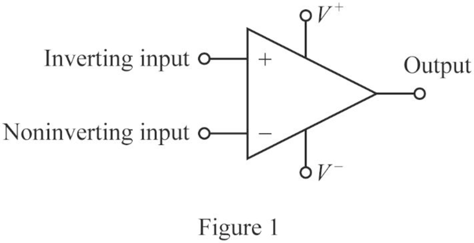
In Figure 1, the op amp has two inputs and one output. Two input terminals are named as inverting input and noninverting input terminals.
The inputs marked with the notations
Therefore, the option (c) is correct and the options (a), (b), (d) are incorrect.
Conclusion:
Thus, the correct option is (c) inverting and noninverting.
Want to see more full solutions like this?
Chapter 5 Solutions
Fundamentals of Electric Circuits
Additional Engineering Textbook Solutions
Concepts Of Programming Languages
Vector Mechanics For Engineers
Degarmo's Materials And Processes In Manufacturing
Elementary Surveying: An Introduction To Geomatics (15th Edition)
Starting Out with Programming Logic and Design (5th Edition) (What's New in Computer Science)
Java: An Introduction to Problem Solving and Programming (8th Edition)


- ".I need the correct answers with explanations" A power station has a daily load cycle as under: 260 kwh for 6 hours; 200 kwh for 8 hours: 160 kwh for 4 hours, 100 kwh for 6 hours. If the power station is equipped with 4 units of 75 kw each, calculate (i) daily load factor (ii) plant capacity factor and (iii) daily requirement of fuel in kg if the calorific value of fuel used were 10,000 kcal/kg.arrow_forward"I need the correct answers with explanations" Pick up the correct answer 1. The area under the daily load curve gives A. average load in kw B. units generated in kwh 2. the minimum phase-neutral voltage at which corona A. Visual critical voltage B. Receiving voltage C. plant capacity in kw D. Maximum demand in kw occurs is C. String voltage D. Critical disruptive voltage. 3. If the length of a transmission line increases, its inductance is B. Decreases C. Constant A. Increases 4. Photo cells are connected in parallel in order to D. None of them A. Increase voltage rating B. Increase current rating C. Increase life cells. D. All of the them 5. Which of the following is a high head turbine? A. Pelton turbine B. Francis turbine 6. Best diversity factor will be at: C. Kaplan turbine D. Propeller turbine A. diversity factor 1 7. When the voltage regulation is positive, then receiving voltage is ...... than sending voltage A. Less B. More C. Equal D. None of the them 8. Fill factor of solar…arrow_forwardConsider the system shown in Fig. Q4(b). Draw a Bode diagram of the open-loop transfer function, and determine the value of the gain K such that the phase margin is 50° . Also, obtain the gain margin of the system with the determined value of gainarrow_forward
- ".I need the correct answers with explanations" Answer True or False and correct errors if found 1. In a certain Op-Amp. if Ad-3500, Ac-0.35, the CMRR=100dB. 2. The voltage series feedback can increase both input and output impedances. 3. A two-pole Sallen-Key high-pass filter contains one capacitor and two resistors. 4. The main feature of a crystal oscillator is the high frequency operation. Each transistor in a class B power amplifier conducts for the entire input cycle. The Q-point must be centered on the load line for maximum class A output signal swing. 7. The differentiator Op-Amp can convert the triangle waveform into sinewave. Class AB power amplifier eliminates crossover distortion found in pure class A. 9. Wien-bridge oscillators are based on positive feedback circuits. 10. The band-reject filter is composed of multiplication of LPF and HPF.arrow_forward".I need the correct answers with explanations" Pick up the correct answer 1. Station that contain boiler is: A. hydro station B. Diesel station 2. Taking into account cost, most of the D. All of them C. Steam power station high-voltage transmission lines are OC. Either of the above D. None of the ab 3. If the maximum load is equal to plant capacity. The plant capacity factor is: A. Underground. B. Overhead C. >1 D. <1 A. 1 4. Five photocells are connected in parallel, 2V for each cell. The output voltage is A.2.5 V B. zero B. 10 V C.2V) D. 5 V 5. Sum of continuous ratings of all the equipment connected to electric power system is defined as: A. Maximum demand B. Connected load C. Daily average load D. Load variation 6. Cables have more effective in.............. than over head transmission lines B. Capacitance C. Resistance D. All of the abov A. Inductance 7. By which of the following methods string efficiency can be equal. 100% A. Using a guard ring B. Equal insulator voltage C.…arrow_forwardQ3/A unity-feedback system with the forward transfer function G(S)= K S(S+7) is operating with a closed-loop step response that has 15% overshoot. Do the following: a. Evaluate the steady-state error for a unit ramp input. b. Design a lag compensator to improve the steady-state error by a factor of 20 to get a new dominant closed-loop poles S-3.4+ j5.63. place the pole of the lag compensator at s=-0.01 c. Design a lag compensator using OP amp if R1= 100KS2 R2=10 KS2 and R3= 10Karrow_forward
- Find the mathematical expression in fourier series for this output below shown in the image. This must have the terms ao, ak and bkarrow_forwardPlease solve this question step by step handwritten solution and do not use ai or chat gpt please thank youarrow_forwardPlease solve this question step by step hand written solution and do not use ai or chat gpt thank youarrow_forward
 Introductory Circuit Analysis (13th Edition)Electrical EngineeringISBN:9780133923605Author:Robert L. BoylestadPublisher:PEARSON
 Delmar's Standard Textbook Of ElectricityElectrical EngineeringISBN:9781337900348Author:Stephen L. HermanPublisher:Cengage Learning
 Programmable Logic ControllersElectrical EngineeringISBN:9780073373843Author:Frank D. PetruzellaPublisher:McGraw-Hill Education
 Fundamentals of Electric CircuitsElectrical EngineeringISBN:9780078028229Author:Charles K Alexander, Matthew SadikuPublisher:McGraw-Hill Education
 Electric Circuits. (11th Edition)Electrical EngineeringISBN:9780134746968Author:James W. Nilsson, Susan RiedelPublisher:PEARSON
 Engineering ElectromagneticsElectrical EngineeringISBN:9780078028151Author:Hayt, William H. (william Hart), Jr, BUCK, John A.Publisher:Mcgraw-hill Education,