
Concept explainers
Videos
For each configuration in Fig. 5.88, find the individual (not combinations of) elements (voltage sources and/or resistors) that are in series.
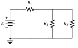
(a)
The individual elements that are connected in series for the given configuration.
Answer to Problem 1P
The individual elements that are connected in series for the given configuration are
Explanation of Solution
Given:
The circuit is given below.
Calculation:
The given circuit is analyzed by the rules of series-parallel combination.
As per the series combination rule,
Conclusion:
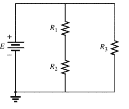
(b)
The individual elements that are connected in series for the given configuration.
Answer to Problem 1P
The individual elements that are connected in series for the given configuration are
Explanation of Solution
Given:
The circuit is given below,
Calculation:
The given circuit is analyzed by the rules of series-parallel combination.
As per the series combination rule,
Conclusion:
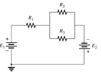
(c)
The individual elements that are connected in series for the given configuration.
Answer to Problem 1P
The individual elements that are connected in series for the given configuration are
Explanation of Solution
Given:
The circuit is given below,
Calculation:
The given circuit is analyzed by the rules of series-parallel combination.
As per the series combination rule,
Conclusion:
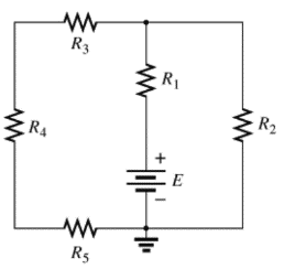
(d)
The individual elements that are connected in series for the given configuration.
Answer to Problem 1P
The individual elements that are connected in series for the given configuration are
Explanation of Solution
Given:
The circuit is given below,
Calculation:
The given circuit is analyzed by the rules of series-parallel combination.As per the series combination rule of resistances,
Conclusion:
Therefore,
Want to see more full solutions like this?
Chapter 5 Solutions
Introductory Circuit Analysis (13th Edition)
Additional Engineering Textbook Solutions
Starting Out with Python (4th Edition)
Mechanics of Materials (10th Edition)
Java: An Introduction to Problem Solving and Programming (8th Edition)
Starting Out with C++ from Control Structures to Objects (9th Edition)
Management Information Systems: Managing The Digital Firm (16th Edition)
Web Development and Design Foundations with HTML5 (8th Edition)


- An AM modulation waveform signal:- p(t)=(8+4 cos 1000πt + 4 cos 2000πt) cos 10000nt (a) Sketch the amplitude spectrum of p(t). (b) Find total power, sideband power and power efficiency. (c) Find the average power containing of each sideband.arrow_forwardCan you rewrite the solution because it is unclear? AM (+) = 8(1+ 0.5 cos 1000kt +0.5 ros 2000ks) = cos 10000 πt. 8 cos wat + 4 cos wit + 4 cos Wat coswet. -Jet jooort J11000 t = 4 e jqooort jgoort +4e + e +e j 12000rt. 12000 kt + e +e jooxt igoo t te (w) = 8ES(W- 100007) + 8IS (W-10000) USBarrow_forwardCan you rewrite the solution because it is unclear? AM (+) = 8(1+0.5 cos 1000kt +0.5 ros 2000 thts) = cos 10000 πt. 8 cos wat + 4 cos wit + 4 cos Wat coswet. J4000 t j11000rt $14+) = 45 jqooort +4e + e + e j 12000rt. 12000 kt + e +e +e Le jsoort -; goon t te +e Dcw> = 885(W- 100007) + 8 IS (W-10000) - USBarrow_forward
- Can you rewrite the solution because it is unclear? Q2 AM ①(+) = 8 (1+0.5 cos 1000πt +0.5 ros 2000kt) $4+) = 45 = *cos 10000 πt. 8 cos wat + 4 cosat + 4 cos Wat coswet. j1000016 +4e -j10000πt j11000Rt j gooort -j 9000 πt + e +e j sooort te +e J11000 t + e te j 12000rt. -J12000 kt + с = 8th S(W- 100007) + 8 IS (W-10000) <&(w) = USB -5-5 -4-5-4 b) Pc 2² = 64 PSB = 42 + 4 2 Pt Pc+ PSB = y = Pe c) Puss = PLSB = = 32 4² = 8 w 32+ 8 = × 100% = 140 (1)³×2×2 31 = 20% x 2 = 3w 302 USB 4.5 5 5.6 6 ms Ac = 4 mi = 0.5 mz Ac = 4 ५ M2 = =0.5arrow_forwardA. Draw the waveform for the following binary sequence using Bipolar RZ, Bipolar NRZ, and Manchester code. Data sequence= (00110100) B. In a binary PCM system, the output signal-to-quantization ratio is to be hold to a minimum of 50 dB. If the message is a single tone with fm-5 kHz. Determine: 1) The number of required levels, and the corresponding output signal-to-quantizing noise ratio. 2) Minimum required system bandwidth.arrow_forwardFind Io using Mesh analysisarrow_forward
- FM station of 100 MHz carrier frequency modulated by a 20 kHz sinusoid with an amplitude of 10 volt, so that the peak frequency deviation is 25 kHz determine: 1) The BW of the FM signal. 2) The approximated BW if the modulating signal amplitude is increased to 50 volt. 3) The approximated BW if the modulating signal frequency is increased by 70%. 4) The amplitude of the modulating signal if the BW is 65 kHz.arrow_forwardAn FDM is used to multiplex two groups of signals using AM-SSB, the first group contains 25 speech signals, each has maximum frequency of 4 kHz, the second group contains 15 music signals, each has maximum frequency of 10 kHz. A guard bandwidth of 500 Hz is used bety each two signals and before the first one. 1. Find the BWmultiplexing 2. Find the BWtransmission if the multiplexing signal is modulated using AM-DSB-LC.arrow_forwardAn FM signal with 75 kHz deviation, has an input signal-to-noise ratio of 18 dB, with a modulating frequency of 15 kHz. 1) Find SNRO at demodulator o/p. 2) Find SNRO at demodulator o/p if AM is used with m=0.3. 3) Compare the performance in case 1) and 2).. Hint: for single tone AM-DSB-LC, SNR₁ = (2m²) (4)arrow_forward
 EBK ELECTRICAL WIRING RESIDENTIALElectrical EngineeringISBN:9781337516549Author:SimmonsPublisher:CENGAGE LEARNING - CONSIGNMENT