
Basic Engineering Circuit Analysis
11th Edition
ISBN: 9781118992661
Author: Irwin, J. David, NELMS, R. M., 1939-
Publisher: Wiley,
expand_more
expand_more
format_list_bulleted
Concept explainers
Videos
Textbook Question
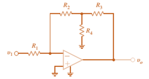
Chapter 4, Problem 42P
Find
Expert Solution & Answer
Want to see the full answer?
Check out a sample textbook solution
Students have asked these similar questions
Can you draw the computed panel board (2nd attached pic) like the panel board management (1st attached pic)?
ps. not graded, i just want to know what it looks like when it draw.
For the circuit shown, let Is = 5, R₁-40, R2-30, R3-100, R4-80, R5-40, R6-30, R7- 10, and Rg= 100, and
find:
R₂
R6
ww
www
VX
R3
R7
R8
RI
R₁₂ Rs
R5
www
• The voltage Vx"
(V)
⚫ The power absorbed by the output resistor Rg: Power=
{Hint: you can use current divider (CD) or any other method.}
(W)
T
For the circuit shown, let V₁ = 26, R1-30, R₂-40, R3-50, R4-20, R5-100, R6-10, and find:
RA
R5
R3
V
(+)
R₁
R₂
R6
www
• The voltage v
(V)
• The power delivered by the power source Vs: Power=
{Hint: you can use voltage divider (VD) or any other method.}
(W)
Chapter 4 Solutions
Basic Engineering Circuit Analysis
Ch. 4 - An amplifier has a gain of 15 and the input...Ch. 4 - An amplifier has a gain of 5 and the output...Ch. 4 - An op-amp based amplifier has supply voltages of...Ch. 4 - For an ideal op-amp, the voltage gain and input...Ch. 4 - Revisit your answers in Problem 4.4 under the...Ch. 4 - Revisit the exact analysis of the inverting...Ch. 4 - Revisit the exact analysis of the inverting...Ch. 4 - An op-amp based amplifier has 18V supplies and a...Ch. 4 - Assuming an ideal op-amp, determine the voltage...Ch. 4 - Assuming an ideal op-amp, determine the voltage...
Ch. 4 - Assuming an ideal op-amp in Fig. P4.11, determine...Ch. 4 - Assuming an ideal op-amp, find the voltage gain of...Ch. 4 - Assuming an ideal op-amp in Fig. P4.13, determine...Ch. 4 - Determine the gain of the amplifier in Fig. P4.14....Ch. 4 - For the amplifier in Fig. P4.15, find the gain and...Ch. 4 - Using the ideal op-amp assumptions, determine the...Ch. 4 - Using the ideal op-amp assumptions, determine...Ch. 4 - In a useful application, the amplifier drives a...Ch. 4 - The op-amp in the amplifier in Fig. P4.19 operates...Ch. 4 - For the amplifier in Fig. P4.20, the maximum value...Ch. 4 - For the circuit in Fig. P4.21, (a) find Vo in...Ch. 4 - Find Vo in the circuit in Fig. P4.22, assuming...Ch. 4 - The network in Fig. P4.23 is a current-to-voltage...Ch. 4 - Prob. 24PCh. 4 - Determine the relationship between v1 and io in...Ch. 4 - Find Vo in the network in Fig. P4.26 and explain...Ch. 4 - Determine the expression for vo in the network in...Ch. 4 - Show that the output of the circuit in Fig. P4.28...Ch. 4 - Find vo in the network in Fig. P4.29.Ch. 4 - Find the voltage gain of the op-amp circuit shown...Ch. 4 - Determine the relationship between and in the...Ch. 4 - Prob. 32PCh. 4 - For the circuit in Fig. P4.33, find the value of...Ch. 4 - Find Vo in the circuit in Fig. P4.34.Ch. 4 - Find Vo in the circuit in Fig. P4.35.Ch. 4 - Determine the expression for the output voltage,...Ch. 4 - Determine the output voltage, of the noninverting...Ch. 4 - Find the input/output relationship for the current...Ch. 4 - Find V0 in the circuit in Fig. P4.39.Ch. 4 - Find Vo in the circuit in Fig. P4.40.Ch. 4 - Find the expression for in the differential...Ch. 4 - Find vo in the circuit in Fig. P4.42.Ch. 4 - Find the output voltage, vo, in the circuit in...Ch. 4 - The electronic ammeter in Example 4.7 has been...Ch. 4 - Given the summing amplifier shown in Fig. 4PFE-l,...Ch. 4 - Determine the output voltage V0 of the summing...Ch. 4 - What is the output voltage V0 in Fig. 4PFE-3. a....Ch. 4 - What value of Rf in the op-amp circuit of Fig....Ch. 4 - What is the voltage Vo in the circuit in Fig....
Additional Engineering Textbook Solutions
Find more solutions based on key concepts
7.13* For a bearing
DE = NUS 5 53’56 ”WT and angles to the right, compute the bearing of PG if angle
DEF 2 88°...
Elementary Surveying: An Introduction To Geomatics (15th Edition)
Write some Java statements that use the String methods indexOf and substring to find the first word in a string...
Java: An Introduction to Problem Solving and Programming (8th Edition)
What causes weld-induced residual stresses?
Degarmo's Materials And Processes In Manufacturing
15. The density of gasoline is 0.72 grams per cubic centimeter [g/cm3]. What is the mass in units of kilograms ...
Thinking Like an Engineer: An Active Learning Approach (4th Edition)
Answer question 3.33, but do not consider any pet having the breed of Unknown.
Database Concepts (8th Edition)
Find the no-load value of υo in the circuit shown.
Find υo when RL is 150 Ω.
How much power is dissipated in th...
Electric Circuits. (11th Edition)
Knowledge Booster


Learn more about
Need a deep-dive on the concept behind this application? Look no further. Learn more about this topic, electrical-engineering and related others by exploring similar questions and additional content below.Similar questions
- In the circuit shown, let R₁-7, R₂-12, R3-24, R4-2, V₁ =17, V2 -68, and V3-51, to calculate the power delivered (or absorbed) by the circuit inside the box, as follows: {NOTE: On Multiple Choice Questions, like this problem, you have only one attempt } 1. The current I is equal to (choose the closed values in amperes) -0.791 0 -0.756 3.022 0.756 (A) -3.022 0.791 2. The power delivered (or absorbed) (choose the closest value in watts) (W) 373.345 0 -373.345 -52.234 52.234 65.079 O-24.833 R₁ V₂ R3 R₂ www V3 V₁ www R4arrow_forwardDetermine X(w) for the given function shown in Figure (1) by applying the differentiation property of the Fourier Transform. x(t) Figure (1) -2 -1 1 2arrow_forwardFor a enahnced-type NMOS transistor with V₁=+1V and kn'(w/L)= 2 mA/V2, find the minimum VDs required to operate in the saturation region when VGS=+2 V. What is the corresponding value of ID?arrow_forward
- . Using Properties to find the Z-Transform including the region of convergence for x(n) = n (2)" cos(0.2π(n − 2))u(n − 1) - -arrow_forwardJ VDD M₁ In the circuit of figure shown below, determine the region of operation of M₁as Vigoes from VDD.to zero. (You may want to draw a plot or just explain by the range, remember the transistor is a PMOS) Assume VDD = 2.5 V and | VTH | = 0.4V. 5 + 1 Varrow_forwardWe wish to design the circuit of the figure shown below for a drain current of 1 mA (l=1mA). If W/L = 18/0.18, compute R1 and R2 such that the input impedance is at least 20 k. R₁ VDD = 1.8 V 500 Ω M₁ R₂arrow_forward
- In the figure shown below, what is the minimum allowable value of VDD if M₁ must not enter the triode region? Assume λ=0 (use ideal current formula that is not dependent on VDs) 1 V + RD VDD = 1.8 V T M 500 Ω 1 W 10 L = 0.18arrow_forwardCalculate the total charge stored in the channel of an NMOS device if Cox=10fF/um², w=10 µm, L=0.1 μm, and VGS-VTH=1 V. Assume VDs=0. (means there is no movement of electrons, all of them are piled up in the channel, we want to calculate the magnitude of electron charge |Q|)arrow_forwardThe first photo is question 1arrow_forward
- a) Write down the order of the transfer function in each of the following cases. Assume that there are no terms in the numerator that will cancel terms in the denominator. 10 H(s) H(s) = s+1 5 (s+3)(s—. 4) 4s1 5 H(s) = H(s) - 83 +1 s27s 6 H(s) H(s) = s(s²+4s) 2s27s+1 84583882 +3s+2 H(s) 83 +8 s+1 = H(s) s34s26s+5 s52s4383 + 4s2 +5s +6arrow_forwardQuestion 5 ( A system is found to have zeros of -3 and poles of 4, and -2. The system also has a gain of 4. Write out the corresponding transfer function. Question 6. A system has a transfer function of What is the gain, K, of the system? Question 7 ( A system has a transfer function of H(s) - 4 8+5 H(s): = 4 8 +5 A step input of size 3 is applied to the system at time zero (Since we're dealing with transfer functions, x(0) is also zero at time zero). a) [10] What is the response ✗(s) of the system? b) [10] Derive the time dependent solution, x(t), of this responsearrow_forwardNote: You might want to do the last question first because the last question asks you to write some python code to calculate the zeros and poles. You could use that code here to help you (except the first problem which you should be able to do by inspection alone) Find the poles and zeros for each of the following transfer functions 1. S+3 H(s) = 8 5 2. H(s): = s238 +1 s2 +48 +3 3. s(s+4) H(s) s3+2s23s 4. 82-586 H(s) = - 8382-68 5. H(s): = s2 +48 +3 s45836s2 - 6arrow_forward
arrow_back_ios
SEE MORE QUESTIONS
arrow_forward_ios
Recommended textbooks for you
 Introductory Circuit Analysis (13th Edition)Electrical EngineeringISBN:9780133923605Author:Robert L. BoylestadPublisher:PEARSON
 Delmar's Standard Textbook Of ElectricityElectrical EngineeringISBN:9781337900348Author:Stephen L. HermanPublisher:Cengage Learning
 Programmable Logic ControllersElectrical EngineeringISBN:9780073373843Author:Frank D. PetruzellaPublisher:McGraw-Hill Education
 Fundamentals of Electric CircuitsElectrical EngineeringISBN:9780078028229Author:Charles K Alexander, Matthew SadikuPublisher:McGraw-Hill Education
 Electric Circuits. (11th Edition)Electrical EngineeringISBN:9780134746968Author:James W. Nilsson, Susan RiedelPublisher:PEARSON
 Engineering ElectromagneticsElectrical EngineeringISBN:9780078028151Author:Hayt, William H. (william Hart), Jr, BUCK, John A.Publisher:Mcgraw-hill Education,
Introductory Circuit Analysis (13th Edition)
Electrical Engineering
ISBN:9780133923605
Author:Robert L. Boylestad
Publisher:PEARSON
Delmar's Standard Textbook Of Electricity
Electrical Engineering
ISBN:9781337900348
Author:Stephen L. Herman
Publisher:Cengage Learning
Programmable Logic Controllers
Electrical Engineering
ISBN:9780073373843
Author:Frank D. Petruzella
Publisher:McGraw-Hill Education
Fundamentals of Electric Circuits
Electrical Engineering
ISBN:9780078028229
Author:Charles K Alexander, Matthew Sadiku
Publisher:McGraw-Hill Education
Electric Circuits. (11th Edition)
Electrical Engineering
ISBN:9780134746968
Author:James W. Nilsson, Susan Riedel
Publisher:PEARSON
Engineering Electromagnetics
Electrical Engineering
ISBN:9780078028151
Author:Hayt, William H. (william Hart), Jr, BUCK, John A.
Publisher:Mcgraw-hill Education,
Nodal Analysis for Circuits Explained; Author: Engineer4Free;https://www.youtube.com/watch?v=f-sbANgw4fo;License: Standard Youtube License