
Basic Engineering Circuit Analysis
11th Edition
ISBN: 9781118992661
Author: Irwin, J. David, NELMS, R. M., 1939-
Publisher: Wiley,
expand_more
expand_more
format_list_bulleted
Concept explainers
Videos
Textbook Question
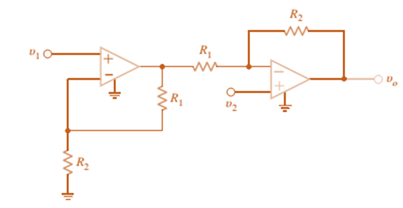
Chapter 4, Problem 40P
Find
Expert Solution & Answer
Want to see the full answer?
Check out a sample textbook solution
Students have asked these similar questions
2) Design the circuit shown in Figure 2 to provide bias current of IQ2= 150 uA.
Assume circuit parameters of IREF2 = 250 UA, V+ = 3 V, and V = -3 V. The
transistor parameters are VTP = -0.6 V, λ = 0, K'p= 40 uA/V², W/Lc = 15 and
W/LA = 25.
V+
Mc
+
VSGC VSGB
+
MB
VSGA
+
+
MA VSDA
IREF2
V-
Figure 2
ww
RD=8kQ
٣/١
a
い
يكا
+91- PU + 96852
A. For the RL-circuit with i(0)=0, Find the current i(t) using LT
R=2
V(t)=sin3t
L=1H
B. Find Invers Laplace Transform for Z(s) =
=
220125
750 x2.01
4s2 +2s+3
s2-3s+2
1) Taking base current into account, determine the value of I copy in each circuit depicted in Fig
1. Normalize the error to nominal value of Icopy.
REF
Vcc
AE
Vcc
QREF
Figure 1- a
I copy
5AE
REF
12
Q₁
copy
Q2
5AE
2AE
ЗАЕ
QREF
Figure 1-b
Chapter 4 Solutions
Basic Engineering Circuit Analysis
Ch. 4 - An amplifier has a gain of 15 and the input...Ch. 4 - An amplifier has a gain of 5 and the output...Ch. 4 - An op-amp based amplifier has supply voltages of...Ch. 4 - For an ideal op-amp, the voltage gain and input...Ch. 4 - Revisit your answers in Problem 4.4 under the...Ch. 4 - Revisit the exact analysis of the inverting...Ch. 4 - Revisit the exact analysis of the inverting...Ch. 4 - An op-amp based amplifier has 18V supplies and a...Ch. 4 - Assuming an ideal op-amp, determine the voltage...Ch. 4 - Assuming an ideal op-amp, determine the voltage...
Ch. 4 - Assuming an ideal op-amp in Fig. P4.11, determine...Ch. 4 - Assuming an ideal op-amp, find the voltage gain of...Ch. 4 - Assuming an ideal op-amp in Fig. P4.13, determine...Ch. 4 - Determine the gain of the amplifier in Fig. P4.14....Ch. 4 - For the amplifier in Fig. P4.15, find the gain and...Ch. 4 - Using the ideal op-amp assumptions, determine the...Ch. 4 - Using the ideal op-amp assumptions, determine...Ch. 4 - In a useful application, the amplifier drives a...Ch. 4 - The op-amp in the amplifier in Fig. P4.19 operates...Ch. 4 - For the amplifier in Fig. P4.20, the maximum value...Ch. 4 - For the circuit in Fig. P4.21, (a) find Vo in...Ch. 4 - Find Vo in the circuit in Fig. P4.22, assuming...Ch. 4 - The network in Fig. P4.23 is a current-to-voltage...Ch. 4 - Prob. 24PCh. 4 - Determine the relationship between v1 and io in...Ch. 4 - Find Vo in the network in Fig. P4.26 and explain...Ch. 4 - Determine the expression for vo in the network in...Ch. 4 - Show that the output of the circuit in Fig. P4.28...Ch. 4 - Find vo in the network in Fig. P4.29.Ch. 4 - Find the voltage gain of the op-amp circuit shown...Ch. 4 - Determine the relationship between and in the...Ch. 4 - Prob. 32PCh. 4 - For the circuit in Fig. P4.33, find the value of...Ch. 4 - Find Vo in the circuit in Fig. P4.34.Ch. 4 - Find Vo in the circuit in Fig. P4.35.Ch. 4 - Determine the expression for the output voltage,...Ch. 4 - Determine the output voltage, of the noninverting...Ch. 4 - Find the input/output relationship for the current...Ch. 4 - Find V0 in the circuit in Fig. P4.39.Ch. 4 - Find Vo in the circuit in Fig. P4.40.Ch. 4 - Find the expression for in the differential...Ch. 4 - Find vo in the circuit in Fig. P4.42.Ch. 4 - Find the output voltage, vo, in the circuit in...Ch. 4 - The electronic ammeter in Example 4.7 has been...Ch. 4 - Given the summing amplifier shown in Fig. 4PFE-l,...Ch. 4 - Determine the output voltage V0 of the summing...Ch. 4 - What is the output voltage V0 in Fig. 4PFE-3. a....Ch. 4 - What value of Rf in the op-amp circuit of Fig....Ch. 4 - What is the voltage Vo in the circuit in Fig....
Additional Engineering Textbook Solutions
Find more solutions based on key concepts
Explain how entities are transformed into tables.
Database Concepts (8th Edition)
22. The Units Society Empire (USE) had defined the following set of "new" units:
Length 1 car = 20 feet [ft]
Ti...
Thinking Like an Engineer: An Active Learning Approach (4th Edition)
A file that contains a Flash animation uses the __________ file extension. a. .class b. .swf c. .mp3 d. .flash
Web Development and Design Foundations with HTML5 (8th Edition)
What is the purpose of testing a program with sample data or input?
Starting Out with Java: From Control Structures through Objects (7th Edition) (What's New in Computer Science)
Assume a telephone signal travels through a cable at two-thirds the speed of light. How long does it take the s...
Electric Circuits. (11th Edition)
In the following exercises, write a program to carry out the task. The program should use variables for each of...
Introduction To Programming Using Visual Basic (11th Edition)
Knowledge Booster


Learn more about
Need a deep-dive on the concept behind this application? Look no further. Learn more about this topic, electrical-engineering and related others by exploring similar questions and additional content below.Similar questions
- 12.2 Evaluate each of the following integrals. (a) G₁: = = √ (31³ +21² + 1) [8(t) +48 (t − 2)] dt -21 (b) G₂ = G2 = 4(e¯2ª +1)[☎(t) −28(t − 2)] dt -2 -20 (c) G3 = 0 3( cos 2π- 1) [8(t) +☎(t − 10)] dt -20arrow_forward3) The differential amplifier in Figure 3 is biased with a three-transistor current source. The transistor parameters are ẞ= 100, VBE (on) = 0.7 V, and VA = ∞. a) Determine I1. Ic2, IC4, VCE2, and VCE4. b) Determine a new value of R1 such that VCE4 = 2.5V. what are the values of Ic4, Ic2, I1, and R₁? +5 V Q1 R₁ = 8.5 ΚΩ IC4 23 RC= • 2 ΚΩ + 24 VCE4 RC= 2 ΚΩ est Ic2 + Q2 VCE2 -5 V Figure 3arrow_forward12.1 Evaluate each of the following integrals: (a) G₁ = √(33-4t²+3)[8(t) +28(t − 2)] dt. (b) G₂ = √442(e³ +1)[8(t) − 28(t − 2)] dt. .16 -31 (c) G3=124t sin(2лt) − 1][§(t − 1) +☎(t − 6)] dt.arrow_forward
- Why is the voltage drop of a self-excited generator greater than the voltagedrop of a separately excited generator?arrow_forwardWhen driving a DC shunt generator with a synchronous prime mover motor, why does the AC amperage to the synchronous motor machine increase as load is added to the generator?arrow_forward100 What is the phase and gain margins of the following system, is it stable or not. Design a PI controller for the following unstable process if any. 50 -120 -130 0 -140 -50 -150 -100 -160 <<-150 -170 -200 -180 10-1 10° 10¹ 102 103 104 105 1071 10° 10¹ 102 103 101 105 Frequency (rad/s) Frequency (rad/s)arrow_forward
- Please assist in the below questionarrow_forwardA. For the RL-circuit with i(0)=0, Find the current i(t) using LT R=2 Ω V(t)=sin3t B. Find Invers Laplace Transform for Z(s) L= 1H 4s2 +2s+3 = s2-3s+2arrow_forwardGiven the circuit diagram in. Find the following voltages: Vda, Vbh, Vgc, Vdi, Vfa, Vac, Vai, Vhf, Vfb, and Vdc.arrow_forward
- L ✓ 30 UF 2mtt The voltage applied across 3-branched circuit of figure 2 is given by v = 100 sin(5000t+ π/4). Calculate the branch currents and total current. v 25ŹR 00arrow_forward10 mA 2 ΚΩ 2 ΚΩ 6 ΚΩ x + ww 4 ΚΩ 4 ΚΩ +1 2 Varrow_forwardFind Vx,V1,V3,V0 according to the case of the circuits using KVLarrow_forward
arrow_back_ios
SEE MORE QUESTIONS
arrow_forward_ios
Recommended textbooks for you
 Introductory Circuit Analysis (13th Edition)Electrical EngineeringISBN:9780133923605Author:Robert L. BoylestadPublisher:PEARSON
 Delmar's Standard Textbook Of ElectricityElectrical EngineeringISBN:9781337900348Author:Stephen L. HermanPublisher:Cengage Learning
 Programmable Logic ControllersElectrical EngineeringISBN:9780073373843Author:Frank D. PetruzellaPublisher:McGraw-Hill Education
 Fundamentals of Electric CircuitsElectrical EngineeringISBN:9780078028229Author:Charles K Alexander, Matthew SadikuPublisher:McGraw-Hill Education
 Electric Circuits. (11th Edition)Electrical EngineeringISBN:9780134746968Author:James W. Nilsson, Susan RiedelPublisher:PEARSON
 Engineering ElectromagneticsElectrical EngineeringISBN:9780078028151Author:Hayt, William H. (william Hart), Jr, BUCK, John A.Publisher:Mcgraw-hill Education,
Introductory Circuit Analysis (13th Edition)
Electrical Engineering
ISBN:9780133923605
Author:Robert L. Boylestad
Publisher:PEARSON
Delmar's Standard Textbook Of Electricity
Electrical Engineering
ISBN:9781337900348
Author:Stephen L. Herman
Publisher:Cengage Learning
Programmable Logic Controllers
Electrical Engineering
ISBN:9780073373843
Author:Frank D. Petruzella
Publisher:McGraw-Hill Education
Fundamentals of Electric Circuits
Electrical Engineering
ISBN:9780078028229
Author:Charles K Alexander, Matthew Sadiku
Publisher:McGraw-Hill Education
Electric Circuits. (11th Edition)
Electrical Engineering
ISBN:9780134746968
Author:James W. Nilsson, Susan Riedel
Publisher:PEARSON
Engineering Electromagnetics
Electrical Engineering
ISBN:9780078028151
Author:Hayt, William H. (william Hart), Jr, BUCK, John A.
Publisher:Mcgraw-hill Education,
Nodal Analysis for Circuits Explained; Author: Engineer4Free;https://www.youtube.com/watch?v=f-sbANgw4fo;License: Standard Youtube License