Basic Engineering Circuit Analysis
11th Edition
ISBN: 9781118992661
Author: Irwin, J. David, NELMS, R. M., 1939-
Publisher: Wiley,
expand_more
expand_more
format_list_bulleted
Concept explainers
Textbook Question
Chapter 4, Problem 4PFE.1TP
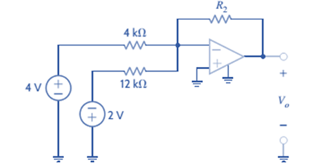
Given the summing amplifier shown in Fig.
a.
b.

Expert Solution & Answer
Want to see the full answer?
Check out a sample textbook solution
Students have asked these similar questions
The first photo is question 1
a) Write down the order of the transfer function in each of the following cases. Assume that
there are no terms in the numerator that will cancel terms in the denominator.
10
H(s)
H(s)
=
s+1
5
(s+3)(s—. 4)
4s1
5
H(s)
=
H(s)
-
83 +1
s27s
6
H(s)
H(s)
=
s(s²+4s)
2s27s+1
84583882 +3s+2
H(s)
83 +8
s+1
=
H(s)
s34s26s+5
s52s4383 + 4s2 +5s +6
Question 5 (
A system is found to have zeros of -3 and poles of 4, and -2. The system also has a gain of
4. Write out the corresponding transfer function.
Question 6.
A system has a transfer function of
What is the gain, K, of the system?
Question 7 (
A system has a transfer function of
H(s)
-
4
8+5
H(s):
=
4
8 +5
A step input of size 3 is applied to the system at time zero (Since we're dealing with transfer
functions, x(0) is also zero at time zero).
a) [10] What is the response ✗(s) of the system?
b) [10] Derive the time dependent solution, x(t), of this response
Chapter 4 Solutions
Basic Engineering Circuit Analysis
Ch. 4 - An amplifier has a gain of 15 and the input...Ch. 4 - An amplifier has a gain of 5 and the output...Ch. 4 - An op-amp based amplifier has supply voltages of...Ch. 4 - For an ideal op-amp, the voltage gain and input...Ch. 4 - Revisit your answers in Problem 4.4 under the...Ch. 4 - Revisit the exact analysis of the inverting...Ch. 4 - Revisit the exact analysis of the inverting...Ch. 4 - An op-amp based amplifier has 18V supplies and a...Ch. 4 - Assuming an ideal op-amp, determine the voltage...Ch. 4 - Assuming an ideal op-amp, determine the voltage...
Ch. 4 - Assuming an ideal op-amp in Fig. P4.11, determine...Ch. 4 - Assuming an ideal op-amp, find the voltage gain of...Ch. 4 - Assuming an ideal op-amp in Fig. P4.13, determine...Ch. 4 - Determine the gain of the amplifier in Fig. P4.14....Ch. 4 - For the amplifier in Fig. P4.15, find the gain and...Ch. 4 - Using the ideal op-amp assumptions, determine the...Ch. 4 - Using the ideal op-amp assumptions, determine...Ch. 4 - In a useful application, the amplifier drives a...Ch. 4 - The op-amp in the amplifier in Fig. P4.19 operates...Ch. 4 - For the amplifier in Fig. P4.20, the maximum value...Ch. 4 - For the circuit in Fig. P4.21, (a) find Vo in...Ch. 4 - Find Vo in the circuit in Fig. P4.22, assuming...Ch. 4 - The network in Fig. P4.23 is a current-to-voltage...Ch. 4 - Prob. 24PCh. 4 - Determine the relationship between v1 and io in...Ch. 4 - Find Vo in the network in Fig. P4.26 and explain...Ch. 4 - Determine the expression for vo in the network in...Ch. 4 - Show that the output of the circuit in Fig. P4.28...Ch. 4 - Find vo in the network in Fig. P4.29.Ch. 4 - Find the voltage gain of the op-amp circuit shown...Ch. 4 - Determine the relationship between and in the...Ch. 4 - Prob. 32PCh. 4 - For the circuit in Fig. P4.33, find the value of...Ch. 4 - Find Vo in the circuit in Fig. P4.34.Ch. 4 - Find Vo in the circuit in Fig. P4.35.Ch. 4 - Determine the expression for the output voltage,...Ch. 4 - Determine the output voltage, of the noninverting...Ch. 4 - Find the input/output relationship for the current...Ch. 4 - Find V0 in the circuit in Fig. P4.39.Ch. 4 - Find Vo in the circuit in Fig. P4.40.Ch. 4 - Find the expression for in the differential...Ch. 4 - Find vo in the circuit in Fig. P4.42.Ch. 4 - Find the output voltage, vo, in the circuit in...Ch. 4 - The electronic ammeter in Example 4.7 has been...Ch. 4 - Given the summing amplifier shown in Fig. 4PFE-l,...Ch. 4 - Determine the output voltage V0 of the summing...Ch. 4 - What is the output voltage V0 in Fig. 4PFE-3. a....Ch. 4 - What value of Rf in the op-amp circuit of Fig....Ch. 4 - What is the voltage Vo in the circuit in Fig....
Knowledge Booster
Learn more about
Need a deep-dive on the concept behind this application? Look no further. Learn more about this topic, electrical-engineering and related others by exploring similar questions and additional content below.Similar questions
- Note: You might want to do the last question first because the last question asks you to write some python code to calculate the zeros and poles. You could use that code here to help you (except the first problem which you should be able to do by inspection alone) Find the poles and zeros for each of the following transfer functions 1. S+3 H(s) = 8 5 2. H(s): = s238 +1 s2 +48 +3 3. s(s+4) H(s) s3+2s23s 4. 82-586 H(s) = - 8382-68 5. H(s): = s2 +48 +3 s45836s2 - 6arrow_forwardWrite python program to plot the zeros and poles if a user provides the coefficients for the numerator and denominator of the transfer function. Since the zeros and poles can be complex, this plot is essentially and argand diagram, where the x axis is the real component and the y axis the imaginary component of a given zero or pole. Create a method called plot-poles zeros(num, den) which takes two lists containing the coefficients. Here is an example and the resulting plot. num [1, 3, 7] # yields zeros at -1.5 +/- 2.17945j den = [1, 4, 5, 3] # yields poles at -2.46557, -0.7672143 +/- 0.7925519j plot_poles_zeros(num, den) Imaginary Page 2 Pole-Zero Plot 3 Zeros × Poles 2 1 -2 1 * Real When you write your code you are only allowed to use the packages numpy and matplotlib. Make sure you label the axes, provide a legend and give a title to your plot (See the example plot). Hint: numpy has a method called roots. When given a list of numbers corresponding to the coefficients of a polynomial,…arrow_forwarda) [10] Compute the zeros and poles for the following transfer function: $2 +5s+6 H(s): s2 +3s+2 b) [10] Factor both polynomials in the numerator and denominator. What does this tell you about one of the poles and zeros you found in a)?arrow_forward
- Pls show neat and whole solutionarrow_forward2. Find the steady-state current i(t) in the circuit shown below when Vs(t) = 100cos(500t -30) volts. Express your answer in cosine form i.e., i(t) Im cos (oot+). (20 pts) LLE) 10052 Vs (E) 40uF 0.3 Harrow_forward1. Determine the thevenin equivalent circuit (i.e., Vth, Zth) from the terminals a-b in the circuit shown below. (15 pts) j512 1052 1020arrow_forward
- Need schematic diagram for this computerized don't use guidelines answer okk will dislikearrow_forwardthe question with its answer but i still dont see how the expansion and the calculation done. please show detailed steps.arrow_forwardQ6) Find the current density J for the magnetic field intensity vectors: (a) H = x²yax + y²zay - 2xzaz pzap + p³a + 3pz²a (b) H = sin cos (c) H = a,arrow_forward
arrow_back_ios
SEE MORE QUESTIONS
arrow_forward_ios
Recommended textbooks for you
 Delmar's Standard Textbook Of ElectricityElectrical EngineeringISBN:9781337900348Author:Stephen L. HermanPublisher:Cengage Learning

Delmar's Standard Textbook Of Electricity
Electrical Engineering
ISBN:9781337900348
Author:Stephen L. Herman
Publisher:Cengage Learning
What is a Power Amplifier, And Do I Need One?; Author: Sweetwater;https://www.youtube.com/watch?v=2wkmSm4V00M;License: Standard Youtube License