
Basic Engineering Circuit Analysis
11th Edition
ISBN: 9781118992661
Author: Irwin, J. David, NELMS, R. M., 1939-
Publisher: Wiley,
expand_more
expand_more
format_list_bulleted
Concept explainers
Videos
Textbook Question
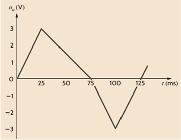
Chapter 4, Problem 3P
An op-amp based amplifier has supply voltages of
(a) Sketch the input waveform from the output waveform in Fig. P4.3.
(b) Double the amplitude of your results in (a) and sketch the new output waveform.
Expert Solution & Answer
Want to see the full answer?
Check out a sample textbook solution
Students have asked these similar questions
a
step
Oster D
Ramp
ess??
Lead-Lag compensater
100
S(S+50
Bafter compensator
KP
K=Y
Telo
Phase
Lead
Phase
Lag
100
SCS+5
Zoe
9=013
P=5
Z-65
T=10
K-032
b=10
T=100
S+312
Sta2
Lead
S
T=1
k=0.2
How can I calculate (ess) from A and B &
"Please, the answer must be documented from a
book, experience, or accurate information without
using artificial intelligence."
Write an Arduino program that flash ON the 4-LED's by using
two switches according to the following scenarios:
1. when S₁=1 then L3, L4 are ON.
2. when S₁=0 then L1,L2 are ON.
3. when S2=1 then L2,L4 are ON.
4. when S2-0 then L₁,L3 are ON.
140
Both circuit do it multisim okk don't use guidelines will dislike okk
Chapter 4 Solutions
Basic Engineering Circuit Analysis
Ch. 4 - An amplifier has a gain of 15 and the input...Ch. 4 - An amplifier has a gain of 5 and the output...Ch. 4 - An op-amp based amplifier has supply voltages of...Ch. 4 - For an ideal op-amp, the voltage gain and input...Ch. 4 - Revisit your answers in Problem 4.4 under the...Ch. 4 - Revisit the exact analysis of the inverting...Ch. 4 - Revisit the exact analysis of the inverting...Ch. 4 - An op-amp based amplifier has 18V supplies and a...Ch. 4 - Assuming an ideal op-amp, determine the voltage...Ch. 4 - Assuming an ideal op-amp, determine the voltage...
Ch. 4 - Assuming an ideal op-amp in Fig. P4.11, determine...Ch. 4 - Assuming an ideal op-amp, find the voltage gain of...Ch. 4 - Assuming an ideal op-amp in Fig. P4.13, determine...Ch. 4 - Determine the gain of the amplifier in Fig. P4.14....Ch. 4 - For the amplifier in Fig. P4.15, find the gain and...Ch. 4 - Using the ideal op-amp assumptions, determine the...Ch. 4 - Using the ideal op-amp assumptions, determine...Ch. 4 - In a useful application, the amplifier drives a...Ch. 4 - The op-amp in the amplifier in Fig. P4.19 operates...Ch. 4 - For the amplifier in Fig. P4.20, the maximum value...Ch. 4 - For the circuit in Fig. P4.21, (a) find Vo in...Ch. 4 - Find Vo in the circuit in Fig. P4.22, assuming...Ch. 4 - The network in Fig. P4.23 is a current-to-voltage...Ch. 4 - Prob. 24PCh. 4 - Determine the relationship between v1 and io in...Ch. 4 - Find Vo in the network in Fig. P4.26 and explain...Ch. 4 - Determine the expression for vo in the network in...Ch. 4 - Show that the output of the circuit in Fig. P4.28...Ch. 4 - Find vo in the network in Fig. P4.29.Ch. 4 - Find the voltage gain of the op-amp circuit shown...Ch. 4 - Determine the relationship between and in the...Ch. 4 - Prob. 32PCh. 4 - For the circuit in Fig. P4.33, find the value of...Ch. 4 - Find Vo in the circuit in Fig. P4.34.Ch. 4 - Find Vo in the circuit in Fig. P4.35.Ch. 4 - Determine the expression for the output voltage,...Ch. 4 - Determine the output voltage, of the noninverting...Ch. 4 - Find the input/output relationship for the current...Ch. 4 - Find V0 in the circuit in Fig. P4.39.Ch. 4 - Find Vo in the circuit in Fig. P4.40.Ch. 4 - Find the expression for in the differential...Ch. 4 - Find vo in the circuit in Fig. P4.42.Ch. 4 - Find the output voltage, vo, in the circuit in...Ch. 4 - The electronic ammeter in Example 4.7 has been...Ch. 4 - Given the summing amplifier shown in Fig. 4PFE-l,...Ch. 4 - Determine the output voltage V0 of the summing...Ch. 4 - What is the output voltage V0 in Fig. 4PFE-3. a....Ch. 4 - What value of Rf in the op-amp circuit of Fig....Ch. 4 - What is the voltage Vo in the circuit in Fig....
Knowledge Booster


Learn more about
Need a deep-dive on the concept behind this application? Look no further. Learn more about this topic, electrical-engineering and related others by exploring similar questions and additional content below.Similar questions
- "Please, the answer must be documented from a book, experience, or accurate information without using artificial intelligence." Write an Arduino program to read the status of two push buttons connected to pins 2&3 respectively and flash ON two LED's connected to pins 12&13 respectively according to the following scenario: If pin 2 is HIGH let LED 12 flash with delay of 400ms, and if pin 3 HIGH, let LED 13 flash ON with delay of 300ms.arrow_forward"Based on a source, book, or expertise in the specialized field, I need a solution to the question." Write an Arduino program code that controls the intensity of each LED (Ascending and descending) connected to pins {3, 5, 6, 9, 10, 11} successively at an array method) an interval one of one second. (Hint usearrow_forward"Based on a source, book, or expertise in the specialized field, I need a solution to the question." Write an Arduino program to control water tank levels, The 1st Tank level is monitored by ultrasonic sensor No.1, connected to pin Ao on the Arduino board and it's linked to a valve via port 7 to regulate the valve's opening and closing. Similarly, 2nd tank is monitored by ultrasonic sensor No.2, connected to pin A1, and linked to a valve through port 8. Follow the rules in the Table below to control valve and motor activation via port 13 with a 500 ms delay: TRIYAH UN Water level Tank Tank 1<500 (Threshold) Tank 2<300 Tank 1==500 Tank 2<300 Tank 1<500 Tank 2==300 Tank 1=500 Tank 2=300 Motor ON ON SON OFF Valve 1 ON OFF ON OFF Valve 2 ON ON OFF OFFarrow_forward
- "Based on a source, book, or expertise in the specialized field, I need a solution to the question." 1985 Write an Arduino program to flash flash three LED's connected to pins (7, 9 & 11) respectively as shown in figure below: (Note: T₁-T3-5s & T₂=3s) LED₁ (pin 7) LED2 (pin 9) LED3 (pin 11) T₁ T2 T3 1406arrow_forward"Based on a source, book, or expertise in the specialized field, I need a solution to the question." Write an Arduino programming code that activates eight LEDs connected to pins 0 to 7 successively with an interval of 1 second when switch S₁ connected to pins 8 is turned ON, and all LEDs are activated when switch S₂ connected to pins 9 is turned off. (Hint: use array method).arrow_forwardDetermine X(w) for the given function shown in Figure (1) by applying the differentiation property of the Fourier Transform. 1 x(t) Figure (1) -1 1 2arrow_forward
- 5. Determine an expression for vo as a function of vs in the circuit shown below. Assume the operational amplifier is ideal (10 pts) 162 + + 212 10052} -j 100-52 Noarrow_forward4. A 120 volt rms voltage source supplies 20 Amps rms to a load. The load requires 2,078 watts. What is the reactive power (Vars) and the power factor of the load. Assume the load is inductive. (15pts)arrow_forward6. Determine the rms value of the voltage cyclical waveform shown below. (15 pts) Zv N 시 ما Msec 8arrow_forward
arrow_back_ios
SEE MORE QUESTIONS
arrow_forward_ios
Recommended textbooks for you
 Introductory Circuit Analysis (13th Edition)Electrical EngineeringISBN:9780133923605Author:Robert L. BoylestadPublisher:PEARSON
 Delmar's Standard Textbook Of ElectricityElectrical EngineeringISBN:9781337900348Author:Stephen L. HermanPublisher:Cengage Learning
 Programmable Logic ControllersElectrical EngineeringISBN:9780073373843Author:Frank D. PetruzellaPublisher:McGraw-Hill Education
 Fundamentals of Electric CircuitsElectrical EngineeringISBN:9780078028229Author:Charles K Alexander, Matthew SadikuPublisher:McGraw-Hill Education
 Electric Circuits. (11th Edition)Electrical EngineeringISBN:9780134746968Author:James W. Nilsson, Susan RiedelPublisher:PEARSON
 Engineering ElectromagneticsElectrical EngineeringISBN:9780078028151Author:Hayt, William H. (william Hart), Jr, BUCK, John A.Publisher:Mcgraw-hill Education,
Introductory Circuit Analysis (13th Edition)
Electrical Engineering
ISBN:9780133923605
Author:Robert L. Boylestad
Publisher:PEARSON
Delmar's Standard Textbook Of Electricity
Electrical Engineering
ISBN:9781337900348
Author:Stephen L. Herman
Publisher:Cengage Learning
Programmable Logic Controllers
Electrical Engineering
ISBN:9780073373843
Author:Frank D. Petruzella
Publisher:McGraw-Hill Education
Fundamentals of Electric Circuits
Electrical Engineering
ISBN:9780078028229
Author:Charles K Alexander, Matthew Sadiku
Publisher:McGraw-Hill Education
Electric Circuits. (11th Edition)
Electrical Engineering
ISBN:9780134746968
Author:James W. Nilsson, Susan Riedel
Publisher:PEARSON
Engineering Electromagnetics
Electrical Engineering
ISBN:9780078028151
Author:Hayt, William H. (william Hart), Jr, BUCK, John A.
Publisher:Mcgraw-hill Education,
Electrical Engineering: Ch 5: Operational Amp (2 of 28) Inverting Amplifier-Basic Operation; Author: Michel van Biezen;https://www.youtube.com/watch?v=x2xxOKOTwM4;License: Standard YouTube License, CC-BY