
Videos
(a) Employ mesh analysis to determine the power dissipated by the 1 Ω resistor in the circuit represented schematically by Fig. 4.68. (b) Check your answer using nodal analysis.
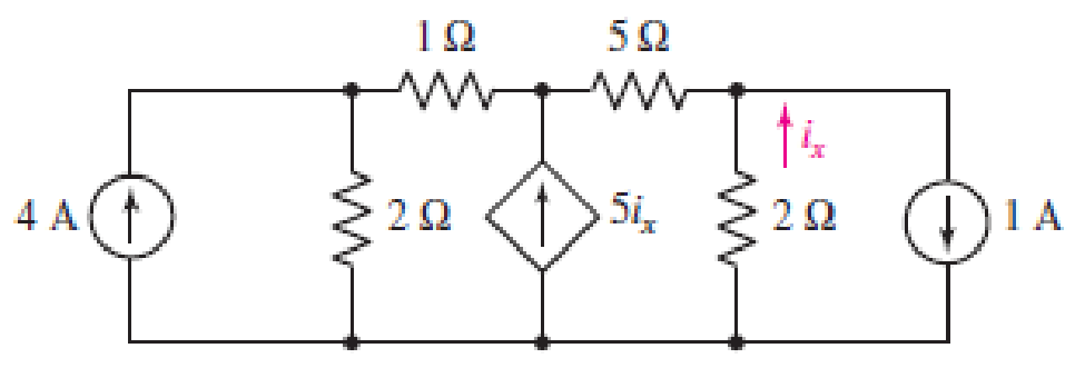
■ FIGURE 4.68
(a)
Employ mess analysis to find the power dissipated by the
Answer to Problem 41E
The power dissipated by the
Explanation of Solution
Calculation:
The circuit diagram is redrawn as shown in Figure 1,
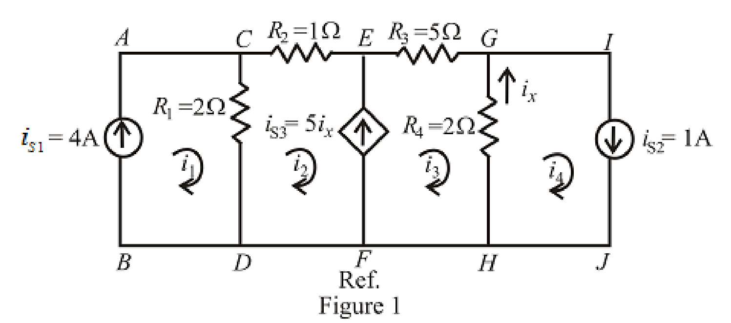
Refer to the redrawn Figure 1,
Apply KVL in the mesh
Here,
The expression for the current flowing in the branch
Here,
The expression for the current flowing in the branch
Here,
The expression for the power dissipated by the
Here,
Refer to the redrawn Figure 1,
Substitute
Rearrange equation (5),
Substitute
Substitute
Substitute
Rearrange the above equation for
Substitute
Rearrange for
Substitute
Substitute
Conclusion:
Thus, the power dissipated by the
(b)
Check the answer by nodal analysis.
Explanation of Solution
Formula used:
Refer to the redrawn Figure 1,
Apply KCL at node
Here,
Apply KCL at node
Here,
The expression for the current flowing in the branch
Apply KCL at node
Here,
The expression for the power dissipated by the
Here,
Calculation:
Refer to the redrawn Figure 1,
Substitute
Substitute
Substitute
Substitute
Substitute
Rearrange equation (13), (14) and (15),
The equations so formed can be written in matrix form as,
Therefore, by Cramer’s rule,
The determinant of the coefficient matrix is as follows,
The 1st determinant is as follows,
The 2nd determinant is as follows,
The 3rd determinant is as follows,
Simplify for
Simplify for
Simplify for
Substitute
So, the power dissipated by the
Conclusion:
Thus, the answer is checked by using nodal analysis.
Want to see more full solutions like this?
Chapter 4 Solutions
ENGINEERING CIRCUIT...(LL)>CUSTOM PKG.<


- An electric car runs on batteries, but needs to make constant stops to re-charge. If a trailer is attached to the car that carries a generator, and the generator is turned by a belt attached to the wheels of the trailer, will the car be able to drive forever without stopping?arrow_forwardA singl core cable of voltage 30 kv. The diameter of Conductor is 3 cm. The diameter of cable is 25 cm. This cable has Two layer of insulator having arelative permittivity 5-3 respectively of The ratio of maximum electric stress of maximum electric stress 8 First layer to the of second layer is 10 Find & 1- The thickness of each layers. 3- The voltage of each layers. §. Layers The saving in radius of cable if another ungrading cable has the Same maximum electric stress, Total village, Conductor diameter of grading cable.arrow_forward66 KV sing care Cable has a drameter of conductor of 3 cm. The radius of cable is 10 cm. This Cable house Two relative permmitivity of insulation 6 and 4 respectively. If The ratio of maximum electric stress of first layer to the maximum eledric streep & second layer is s 1- find the village & each layers. 2- Min- electric stress J Cable 3- Compare the voltage of ungrading Cable has the same distance and relectric stresses.arrow_forward
- Prelab Information 1. Laboratory Preliminary Discussion First-order Low-pass RC Filter Analysis The first-order low-pass RC filter shown in figure 1 below represents all voltages and currents in the time domain. It is of course possible to solve for all circuit voltages using time domain differential equation techniques, but it is more efficient to convert the circuit to its s-domain equivalent as shown in figure 2 and apply Laplace transform techniques. vs(t) i₁(t) + R₁ ww V₁(t) 12(t) Lic(t) Vout(t) = V2(t) R₂ Vc(t) C Vc(t) VR2(t) = V2(t) + Vs(s) Figure 1: A first-order low-pass RC filter represented in the time domain. I₁(s) R1 W + V₁(s) V₂(s) 12(s) Ic(s) + Vout(S) == Vc(s) Vc(s) Zc(s) = = VR2(S) V2(s) Figure 2: A first-order low-pass RC filter represented in the s-domain.arrow_forwarduse matlabarrow_forwardI need help with this problem and an explanation of the solution for the image described below. (Introduction to Signals and Systems)arrow_forward
- How do we know that D1 is forward bias and D2 is reverse biased?arrow_forwardSolve it in a different way than the previous solution that I searched forarrow_forwardA lossless uncharged transmission line of length L = 0.45 cm has a characteristic impedance of 60 ohms. It is driven by an ideal voltage generator producing a pulse of amplitude 10V and width 2 nS. If the transmission line is connected to a load of 200 ohms, sketch the voltage at the load as a function of time for the interval 0 < t < 20 nS. You may assume that the propagation velocity of the transmission is c/2. Answered now answer number 2. Repeat Q.1 but now assume the width of the pulse produced by the generator is 4 nS. Sketch the voltage at the load as a function of time for 0 < t < 20 nS.arrow_forward
- Solve this experiment with an accurate solution, please. Thank you.arrow_forwardA lossless uncharged transmission line of characteristic impedance Zo = 600 and length T = 1us is connected to a 180 load. If this transmission line is connected at t = 0 to a 90 V dc source with an internal resistance of 900, from a bounce diagram of this system sketch (a) the voltage at z=0, z=L, and z = L/2 for up to 7.25μs and (b) calculate the load voltage after an infinite amount of time.arrow_forwardA lossless uncharged transmission line of length L = 0.45 cm has a characteristic impedance of 60 ohms. It is driven by an ideal voltage generator producing a pulse of amplitude 10V and width 2 nS. If the transmission line is connected to a load of 200 ohms, sketch the voltage at the load as a function of time for the interval 0 < t < 20 nS. You may assume that the propagation velocity of the transmission is c/2.arrow_forward
 Introductory Circuit Analysis (13th Edition)Electrical EngineeringISBN:9780133923605Author:Robert L. BoylestadPublisher:PEARSON
 Delmar's Standard Textbook Of ElectricityElectrical EngineeringISBN:9781337900348Author:Stephen L. HermanPublisher:Cengage Learning
 Programmable Logic ControllersElectrical EngineeringISBN:9780073373843Author:Frank D. PetruzellaPublisher:McGraw-Hill Education
 Fundamentals of Electric CircuitsElectrical EngineeringISBN:9780078028229Author:Charles K Alexander, Matthew SadikuPublisher:McGraw-Hill Education
 Electric Circuits. (11th Edition)Electrical EngineeringISBN:9780134746968Author:James W. Nilsson, Susan RiedelPublisher:PEARSON
 Engineering ElectromagneticsElectrical EngineeringISBN:9780078028151Author:Hayt, William H. (william Hart), Jr, BUCK, John A.Publisher:Mcgraw-hill Education,