
ENGINEERING CIRCUIT...(LL)>CUSTOM PKG.<
9th Edition
ISBN: 9781260540666
Author: Hayt
Publisher: MCG CUSTOM
expand_more
expand_more
format_list_bulleted
Concept explainers
Videos
Textbook Question
Chapter 4, Problem 5E
In the circuit of Fig. 4.35, determine the current labeled i with the assistance of nodal analysis techniques.
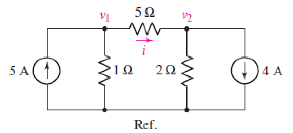
FIGURE 4.35
Expert Solution & Answer
Want to see the full answer?
Check out a sample textbook solution
Students have asked these similar questions
. 30-dB, right-circularly polarized antenna in a radio link radiates 5-W of power
t 2 GHz. The input impedance of this antenna is 75 ohms, and it is attached
ɔ a 50-ohm transmission line.
The receiving antenna has an impedance mismatch at its terminals, -
which leads to a VSWR of 2. The receiving antenna is about 95% efficient and
has a field pattern near the beam maximum given by E, = (2âx + jây) F, (0, 0).
The distance between the two antennas is 4,000 km, and the receiving antenna
Directivity is 100. Determine the Minimum power
Delivered to receiving antenna.
1
Open plc - ladder logic To control traffic, we have red lights to stop cars and green lights to initiate entry/exit.
If a car is in the lane, then the red lights turn ON. If no cars are in the lane, then the
green lights turn ON. Upon turning ON the main switch button, the main switch indicator
should turn ON and the system should start with green lights ON and red lights OFF?
3-4)
3.4-2 Signals g₁(t) = 104П(104) and g2(t) = 8(t) are applied at the inputs of the ideal low-pass
filters H₁(f)=(f/20,000) and H2(f) = П(f/10,000) (Fig. P3.4-2). The outputs y₁ (t) and
y2(t) of these filters are multiplied to obtain the signal y(t) = y1 (1)y2(t).
(a) Sketch G1(f) and G2(f).
(b) Sketch H₁(f) and H₂(f).
(c) Sketch Y₁ (f) and Y2(f).
(d) Find the bandwidths of y₁ (t), y2(t), and y(t).
8₁ (1)
H₁(f)
y, (t)
y(t) = y₁ (1) y2 (1)
82(1)
½⁄2 (1)
H₂(f)
Chapter 4 Solutions
ENGINEERING CIRCUIT...(LL)>CUSTOM PKG.<
Ch. 4.1 - For the circuit of Fig. 4.3, determine the nodal...Ch. 4.1 - For the circuit of Fig. 4.5, compute the voltage...Ch. 4.1 - For the circuit of Fig. 4.8, determine the nodal...Ch. 4.2 - For the circuit of Fig. 4.11, compute the voltage...Ch. 4.3 - Determine i1 and i2 in the circuit in Fig. 4.19....Ch. 4.3 - Determine i1 and i2 in the circuit of Fig 4.21....Ch. 4.3 - Determine i1 in the circuit of Fig. 4.24 if the...Ch. 4.4 - Determine the current i1 in the circuit of Fig....Ch. 4.4 - Determine v3 in the circuit of Fig. 4.28. FIGURE...Ch. 4 - Solve the following systems of equations: (a) 2v2 ...
Ch. 4 - (a) Solve the following system of equations:...Ch. 4 - (a) Solve the following system of equations:...Ch. 4 - Correct (and verify by running) the following...Ch. 4 - In the circuit of Fig. 4.35, determine the current...Ch. 4 - Calculate the power dissipated in the 1 resistor...Ch. 4 - For the circuit in Fig. 4.37, determine the value...Ch. 4 - With the assistance of nodal analysis, determine...Ch. 4 - Prob. 9ECh. 4 - For the circuit of Fig. 4.40, determine the value...Ch. 4 - Use nodal analysis to find vP in the circuit shown...Ch. 4 - Prob. 12ECh. 4 - Prob. 13ECh. 4 - Determine a numerical value for each nodal voltage...Ch. 4 - Prob. 15ECh. 4 - Using nodal analysis as appropriate, determine the...Ch. 4 - Prob. 17ECh. 4 - Determine the nodal voltages as labeled in Fig....Ch. 4 - Prob. 19ECh. 4 - Prob. 20ECh. 4 - Employing supernode/nodal analysis techniques as...Ch. 4 - Prob. 22ECh. 4 - Prob. 23ECh. 4 - Prob. 24ECh. 4 - Repeat Exercise 23 for the case where the 12 V...Ch. 4 - Prob. 26ECh. 4 - Prob. 27ECh. 4 - Determine the value of k that will result in vx...Ch. 4 - Prob. 29ECh. 4 - Prob. 30ECh. 4 - Prob. 31ECh. 4 - Determine the currents flowing out of the positive...Ch. 4 - Obtain numerical values for the two mesh currents...Ch. 4 - Use mesh analysis as appropriate to determine the...Ch. 4 - Prob. 35ECh. 4 - Prob. 36ECh. 4 - Find the unknown voltage vx in the circuit in Fig....Ch. 4 - Prob. 38ECh. 4 - Prob. 39ECh. 4 - Determine the power dissipated in the 4 resistor...Ch. 4 - (a) Employ mesh analysis to determine the power...Ch. 4 - Define three clockwise mesh currents for the...Ch. 4 - Prob. 43ECh. 4 - Prob. 44ECh. 4 - Prob. 45ECh. 4 - Prob. 46ECh. 4 - Prob. 47ECh. 4 - Prob. 48ECh. 4 - Prob. 49ECh. 4 - Prob. 50ECh. 4 - Prob. 51ECh. 4 - Prob. 52ECh. 4 - For the circuit represented schematically in Fig....Ch. 4 - The circuit of Fig. 4.80 is modified such that the...Ch. 4 - The circuit of Fig. 4.81 contains three sources....Ch. 4 - Solve for the voltage vx as labeled in the circuit...Ch. 4 - Consider the five-source circuit of Fig. 4.83....Ch. 4 - Replace the dependent voltage source in the...Ch. 4 - After studying the circuit of Fig. 4.84, determine...Ch. 4 - Prob. 60ECh. 4 - Employ LTspice (or similar CAD tool) to verify the...Ch. 4 - Employ LTspice (or similar CAD tool) to verify the...Ch. 4 - Employ LTspice (or similar CAD tool) to verify the...Ch. 4 - Verify numerical values for each nodal voltage in...Ch. 4 - Prob. 65ECh. 4 - Prob. 66ECh. 4 - Prob. 67ECh. 4 - Prob. 68ECh. 4 - Prob. 69ECh. 4 - (a) Under what circumstances does the presence of...Ch. 4 - Referring to Fig. 4.88, (a) determine whether...Ch. 4 - Consider the LED circuit containing a red, green,...Ch. 4 - The LED circuit in Fig. 4.89 is used to mix colors...Ch. 4 - A light-sensing circuit is in Fig. 4.90, including...Ch. 4 - Use SPICE to analyze the circuit in Exercise 74 by...
Knowledge Booster


Learn more about
Need a deep-dive on the concept behind this application? Look no further. Learn more about this topic, electrical-engineering and related others by exploring similar questions and additional content below.Similar questions
- solve the differential equation y'' -2y'-3y=x³e^5x cos(3x) Don't use AI,I need it handwrittenarrow_forward3-3) Similar to Lathi & Ding prob. 3.3-7. The signals in the figure below are modulated signals with carrier cos(5t). Find the Fourier transforms of these signals using the appropriate properties of the Fourier transform and text Table 3.1. The sketch the magnitude and phase spectra for figure parts (a) and (b). Hint: these functions can be expressed in the form g(t) cos(2лfot) (a) 1 1 2π www. σπ (b) (c) όπarrow_forward3-1) Similar to Lathi & Ding prob. 3.1-1. Use direct integration to find the Fourier transforms of the signals shown below. a) g₁(t) = II(t − 2) + 2 exp (−3|t|) b) g(t) = d(t+2)+3e¯u (t − 2)arrow_forward
- Fundamentals of Energy Systems HW 4 Q6arrow_forwardConstruct a battery pack to deliver 360V and 450-mile range for a vehicle that consumes 200 Wh/mile, from prismatic cells with 25Ah and 3.6 V. Physical dimensions of the cell are 0.5 cm thickness, 20 cm width and 40 cm length. a) Report configuration of the battery pack. 10-points b) Resistance of each cell is 0.05 Ohm, calculate the total internal resistance of the battery pack. 10-points c) Calculate the voltage drop during discharge when the battery is discharged at 100A. 10-points d) Calculate the amount of anode and cathode to build a prismatic cell with 25Ah capacity. Assume the cell chemistry as: Si anode and [Li(Ni1/3Co1/3Mn1/3)O2] cathode. Atomic weight of elements: Li=7, Si = 28, Ni=58, Co=59, Mn=55, O=16, 10-points e) Calculate the theoretical specific energy (Wh/kg) and practical energy density (Wh/liter) of the battery pack. 10-points f) Calculate the thickness on anode and cathode coating assuming each electrode has 30%…arrow_forwardI need help with this problem and an explanation of the solution for the image described below. (Introduction to Signals and Systems)arrow_forward
arrow_back_ios
SEE MORE QUESTIONS
arrow_forward_ios
Recommended textbooks for you
 Introductory Circuit Analysis (13th Edition)Electrical EngineeringISBN:9780133923605Author:Robert L. BoylestadPublisher:PEARSON
 Delmar's Standard Textbook Of ElectricityElectrical EngineeringISBN:9781337900348Author:Stephen L. HermanPublisher:Cengage Learning
 Programmable Logic ControllersElectrical EngineeringISBN:9780073373843Author:Frank D. PetruzellaPublisher:McGraw-Hill Education
 Fundamentals of Electric CircuitsElectrical EngineeringISBN:9780078028229Author:Charles K Alexander, Matthew SadikuPublisher:McGraw-Hill Education
 Electric Circuits. (11th Edition)Electrical EngineeringISBN:9780134746968Author:James W. Nilsson, Susan RiedelPublisher:PEARSON
 Engineering ElectromagneticsElectrical EngineeringISBN:9780078028151Author:Hayt, William H. (william Hart), Jr, BUCK, John A.Publisher:Mcgraw-hill Education,
Introductory Circuit Analysis (13th Edition)
Electrical Engineering
ISBN:9780133923605
Author:Robert L. Boylestad
Publisher:PEARSON
Delmar's Standard Textbook Of Electricity
Electrical Engineering
ISBN:9781337900348
Author:Stephen L. Herman
Publisher:Cengage Learning
Programmable Logic Controllers
Electrical Engineering
ISBN:9780073373843
Author:Frank D. Petruzella
Publisher:McGraw-Hill Education
Fundamentals of Electric Circuits
Electrical Engineering
ISBN:9780078028229
Author:Charles K Alexander, Matthew Sadiku
Publisher:McGraw-Hill Education
Electric Circuits. (11th Edition)
Electrical Engineering
ISBN:9780134746968
Author:James W. Nilsson, Susan Riedel
Publisher:PEARSON
Engineering Electromagnetics
Electrical Engineering
ISBN:9780078028151
Author:Hayt, William H. (william Hart), Jr, BUCK, John A.
Publisher:Mcgraw-hill Education,
Nodal Analysis for Circuits Explained; Author: Engineer4Free;https://www.youtube.com/watch?v=f-sbANgw4fo;License: Standard Youtube License