
Concept explainers
Videos
Use SPICE to analyze the circuit in Exercise 74 by doing the following. (a) Simulate the circuit for varying values of Rpot to balance the circuit at 500 lux, where Rlight = 200 Ω. It is helpful to use a parameter sweep by defining a variable such as {potentiometer} (including the curly brackets) in the value for Rpot, and a SPICE directive such as .step param potentiometer 150 250 2 to step the variable from 150 to 250 in steps of 2. (b) If the resistance of the photoresistor decreases by 2% for for a light increase to 600 lux, use SPICE to find the resulting output voltage Vout.
74. A light-sensing circuit is in Fig. 4.90, including a resistor that changes value under illumination (photoresistor Rlight) and a variable resistor (potentiometer Rpot). The circuit is in the Wheatstone bridge configuration such that a “balanced” condition results in Vout = 0 for a defined value of incident light and a corresponding value for Rlight. (a) Derive an algebraic expression for Vout in terms of RS, R1, R2, Rlight, and Rpot. (b) Using the numerical values given in the circuit, calculate the value of Rpot required to balance the circuit at 500 lux, where Rlight = 200 Ω. (c) If the resistance of the photoresistor decreases by 2% for a light increase to 600 lux (and assuming the resistance change with light is linear), what will the light level be if you measure Vout = 150 mV?
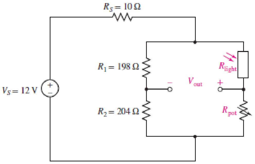
■ FIGURE 4.90
Want to see the full answer?
Check out a sample textbook solution
Chapter 4 Solutions
ENGINEERING CIRCUIT...(LL)>CUSTOM PKG.<


- Q4) Given the magnetic vector potential: A = y²z ax-(x + 1)z² az A/m Find(a) the magnetic flux density; (b)the magnetic flux through a square loop described by 0≤x≤1, 0 ≤ y ≤1, z=2.arrow_forwardQ5) Consider the following arbitrary fields. Find out which of them can possibly represent electrostatic or magnetostatic field in free space. (a) A = y cos axa, + (y + ea, (b) B 20 р (c) C = r² sin 0 aarrow_forwardEx. 12 plane y=l carries current k = 50āz Find at- roro) ره α)- ⑥(1.5-3). Hw marrow_forward
- Please, my dear teacher, solve the question on a piece of paper, not with artificial intelligence, then show the final matrix in the solution. Subject the Control Systemarrow_forwardAn Aluminum wire 2250Ft long cannot have a resistance greater than 0.2 ohms. What is the minimum size of wire that may be used?arrow_forwardCalculate the resistance for Aluminum wire, 8 AWG with a length of 1000 FT*arrow_forward
- Introduction The circuit of Fig. 1 is required to be modeled using a state - space representation, where 2 states will be used, based on the number of the energy - storing elements of the circuit, the capacitor and the inductor. u(t) + ΙΩ www 13 F 5 Ω it (t) www vc(t) 1 H Figure 1: LCR circuit The input signal to the circuit is the voltage u(t) in Volts and the output signal is the voltage across the capacitor, vc(t). Questions 1. Choice of system states: Choose appropriate signals for the 2 states of the system. x₁(t) = i₁(t) x₂ (t) =arrow_forward5. State transition matrix: (t), which is defined as, Calculate analytically the state transition matrix (t) = et = L¯¹{(sI – A)¯¹} Show that the answer is the following, 1 e-4t cos(√2t) - e-4 sin(√2 t) 1 e -4t √2 (t) = et -3 1 -4t sin (√2 t) e COS -4t cos (√2t) + - e sin(√2 t) 2-4t sin(√2 t)| Calculate the following: (SI - A)-1= Use the completion - in - the-square technique (CASE 3) to calculate the inverse Laplace: L¯¹{(SI - A)¯¹} =arrow_forwardA single-core cable working on 66 kV has a conductor diameter of 2 cm and the sheath of inside diameter is 10 cm. If two metallic intersheaths of diameters 5 cm, 8 cm respectively are used for grading the cable.. If the maximum electric stress is the same for each layers. 1- Find the voltage of each metallic intersheaths. 2- Find the thickness of each layers.arrow_forward
 Introductory Circuit Analysis (13th Edition)Electrical EngineeringISBN:9780133923605Author:Robert L. BoylestadPublisher:PEARSON
 Delmar's Standard Textbook Of ElectricityElectrical EngineeringISBN:9781337900348Author:Stephen L. HermanPublisher:Cengage Learning
 Programmable Logic ControllersElectrical EngineeringISBN:9780073373843Author:Frank D. PetruzellaPublisher:McGraw-Hill Education
 Fundamentals of Electric CircuitsElectrical EngineeringISBN:9780078028229Author:Charles K Alexander, Matthew SadikuPublisher:McGraw-Hill Education
 Electric Circuits. (11th Edition)Electrical EngineeringISBN:9780134746968Author:James W. Nilsson, Susan RiedelPublisher:PEARSON
 Engineering ElectromagneticsElectrical EngineeringISBN:9780078028151Author:Hayt, William H. (william Hart), Jr, BUCK, John A.Publisher:Mcgraw-hill Education,