
Loose Leaf for Engineering Circuit Analysis Format: Loose-leaf
9th Edition
ISBN: 9781259989452
Author: Hayt
Publisher: Mcgraw Hill Publishers
expand_more
expand_more
format_list_bulleted
Concept explainers
Videos
Textbook Question
Chapter 3.4, Problem 5P
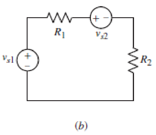
In the circuit of Fig. 3.12b, vs1 = 120 V, vs2 = 30 V, R1 = 30 Ω, and R2 = 15 Ω. Compute the power absorbed by each element.
Expert Solution & Answer
Want to see the full answer?
Check out a sample textbook solution
Students have asked these similar questions
"Can you explain the method of choosing the
direction?"
Question- A plane wave in a non-magnetic medium
=
Нр 1 has an electric field-
E = 50 sin(10®t +2)ây
V
m
The standard equation of the electric field is- How can
E = Eosin(t + Bây
V
m
✓ explan how
(C. i)- The direction of the propagation is-âk = - âz
the direction
|
Express this graph/signal as a sum of singularity functions. Please give a proper solution.
2) A 208 V, four-pole, 60 Hz, Y-connected, wound-rotor induction motor has a rated power of 30 HP. The components of its equivalent circuit are R1 = 0.100
R2 = 0.070
XM = 10.0
X1 = 0.210
X2 = 0.210
Pmec = 500 W
Psup ~ 0
Pcore = 400 W
For a slip of 0.05, find:
a) The line current
b) The stator copper losses PcE
c) The air gap power PEF
d) The power converted from mechanical to electrical form Pconv
e) The induced torque _ind
f) load torque _load
g) The total efficiency of the machine
h) The speed of the motor in revolutions per minute and in radians per second
Chapter 3 Solutions
Loose Leaf for Engineering Circuit Analysis Format: Loose-leaf
Ch. 3.2 - 3.1 (a) Count the number of branches and nodes in...Ch. 3.3 - Determine ix and vx in the circuit of Fig. 3.7....Ch. 3.3 - For the circuit of Fig. 3.9, if vR1=1V, determine...Ch. 3.3 - Determine vx in the circuit of Fig. 3.11.Ch. 3.4 - In the circuit of Fig. 3.12b, vs1 = 120 V, vs2 =...Ch. 3.4 - 3.6 In the circuit of Fig. 3.14, find the power...Ch. 3.5 - Determine v in the circuit of Fig. 3.16.Ch. 3.5 - For the single-node-pair circuit of Fig. 3.18,...Ch. 3.6 - Determine the current i in the circuit of Fig....Ch. 3.6 - Determine the voltage v in the circuit of Fig....
Ch. 3.6 - Determine whether the circuit of Fig. 3.25...Ch. 3.7 - 3.12 Determine a single-value equivalent...Ch. 3.7 - 3.13 Determine i in the circuit of Fig. 3.29....Ch. 3.7 - Determine v in the circuit of Fig. 3.31 by first...Ch. 3.7 - 3.15 For the circuit of Fig. 3.33, calculate the...Ch. 3.8 - 3.16 Use voltage division to determine vx in the...Ch. 3.8 - In the circuit of Fig. 3.40, use resistance...Ch. 3 - Referring to the circuit depicted in Fig. 3.45,...Ch. 3 - Referring to the circuit depicted in Fig. 3.46,...Ch. 3 - For the circuit of Fig. 3.47: (a) Count the number...Ch. 3 - For the circuit of Fig. 3.47: (a) Count the number...Ch. 3 - Refer to the circuit of Fig. 3.48, and answer the...Ch. 3 - A local restaurant has a neon sign constructed...Ch. 3 - Referring to the single-node diagram of Fig. 3.50,...Ch. 3 - Determine the current labeled I in each of the...Ch. 3 - In the circuit shown in Fig. 3.52, the resistor...Ch. 3 - The circuit of Fig. 3.53 represents a system...Ch. 3 - In the circuit depicted in Fig. 3.54, ix is...Ch. 3 - For the circuit of Fig. 3.55 (which employs a...Ch. 3 - Determine the current labeled I3 in the circuit of...Ch. 3 - Study the circuit depicted in Fig. 3.57, and...Ch. 3 - Prob. 15ECh. 3 - For the circuit of Fig. 3.58: (a) Determine the...Ch. 3 - For each of the circuits in Fig. 3.59, determine...Ch. 3 - Use KVL to obtain a numerical value for the...Ch. 3 - Prob. 19ECh. 3 - In the circuit of Fig. 3.55, calculate the voltage...Ch. 3 - Determine the value of vx as labeled in the...Ch. 3 - Consider the simple circuit shown in Fig. 3.63....Ch. 3 - (a) Determine a numerical value for each current...Ch. 3 - The circuit shown in Fig. 3.65 includes a device...Ch. 3 - The circuit of Fig. 3.12b is constructed with the...Ch. 3 - Obtain a numerical value for the power absorbed by...Ch. 3 - Compute the power absorbed by each element of the...Ch. 3 - Compute the power absorbed by each element in the...Ch. 3 - Kirchhoffs laws apply whether or not Ohms law...Ch. 3 - Referring to the circuit of Fig. 3.70, (a)...Ch. 3 - Determine a value for the voltage v as labeled in...Ch. 3 - Referring to the circuit depicted in Fig. 3.72,...Ch. 3 - Determine the voltage v as labeled in Fig. 3.73,...Ch. 3 - Although drawn so that it may not appear obvious...Ch. 3 - Determine the numerical value for veq in Fig....Ch. 3 - Determine the numerical value for ieq in Fig....Ch. 3 - For the circuit presented in Fig. 3.76. determine...Ch. 3 - Determine the value of v1 required to obtain a...Ch. 3 - (a) For the circuit of Fig. 3.78, determine the...Ch. 3 - What value of IS in the circuit of Fig. 3.79 will...Ch. 3 - (a) Determine the values for IX and VY in the...Ch. 3 - Determine the equivalent resistance of each of the...Ch. 3 - For each network depicted in Fig. 3.82, determine...Ch. 3 - (a) Simplify the circuit of Fig. 3.83 as much as...Ch. 3 - (a) Simplify the circuit of Fig. 3.84, using...Ch. 3 - Making appropriate use of resistor combination...Ch. 3 - Calculate the voltage labeled vx in the circuit of...Ch. 3 - Determine the power absorbed by the 15 resistor...Ch. 3 - Calculate the equivalent resistance Req of the...Ch. 3 - Show how to combine four 100 resistors to obtain...Ch. 3 - Prob. 51ECh. 3 - Prob. 52ECh. 3 - Prob. 53ECh. 3 - Prob. 54ECh. 3 - Prob. 55ECh. 3 - Prob. 56ECh. 3 - Prob. 57ECh. 3 - Prob. 58ECh. 3 - Prob. 59ECh. 3 - Prob. 60ECh. 3 - With regard to the circuit shown in Fig. 3.98,...Ch. 3 - Delete the leftmost 10 resistor in the circuit of...Ch. 3 - Consider the seven-element circuit depicted in...
Knowledge Booster


Learn more about
Need a deep-dive on the concept behind this application? Look no further. Learn more about this topic, electrical-engineering and related others by exploring similar questions and additional content below.Similar questions
- 5. There are three sources that would affect the current flow in this circuit. Find the current through the 4k2 resistor that is caused solely by the 24V source (i.e., remove the 2mA and 12V sources using the correct methods). (20 points) 24 V + 9k, ww www 4kS 2mA 24ΚΩ www ++ 12V www 6k 24ΚΩarrow_forward"Can you explain the method of finding the direction?" the electric field in free space is given by ety E: 50 Cos [2π 10 t - Bz ] a) find the direction of the wave propagation b) Calculate W, B, A, S V/marrow_forwardAthle phase a.c. distributor AB has: The distance from A to B is 500 m. The distance from A to C is 800 m. The impedance of each section is (6+j 8) /km. A B C The voltage at the far end is maintained at 250 volt. Find: sending voltage, sending current, supply power factor and 80 A 60 A total voltage drop. 0.8 lag. P.f 0.6 lead. p.farrow_forward
- The transfer function H(s) = Y(s)/X(s) = Vo(s)/Vi(s) should be found from the circuit given that the initial conditions are equal to 0. Do not answer using AI Chatbots. PLEASEarrow_forwardA 10kW, 230V, long shunt compound DC generator has efficiency = 82%, armature resistance = 0.15 ohms, series field resistance = 0.1 ohm, shunt field resistance = 100 ohms. What are: armature current, armature voltage across the brushes, generated emf, total copper losses, and horsepower of prime mover?arrow_forwardThe capacitors in the circuit shown below have no energy stored in them and then switch “A” closes at time t=0. Find v(t) across the 6 uF capacitor for t≥0arrow_forward
- Consider the circuit Below: A) Find and show the Thevenin equivalent with respect to terminals a,b B) Find and show the Norton equivalent with respect to terminals a,b C)Find the value of Ro and the maximum power delivered across it when its adjusted such that the power across it is the maximum possible when connected in this fashionarrow_forwardConsider the Circuit Below: A)Find Vo if Vin is 0.2 volts and the positive and negative power supply voltages are +15v and -15v respectively. B)What is the Maximum of Vin that will not hit saturation for this circuit?arrow_forwardA shunt generator is rated at 125V, 25KW; armature resistance is 0.08 ohms, shunt field resistance is 25 ohms. What are: Armature voltage at rated load, armature power loss, shunt field power loss Total power generated in the armature?arrow_forward
- A 12KW, 240V 1500RPM shunt generator has an armature resistance of .02 ohm and a shunt field resistance of 160 ohms. The stray power losses are 900W. Assuming a constant shunt field current, what (1) the efficiency at rated load and (2) the efficiency of the generator at half-rated load?arrow_forward4. Consider the three circuits shown in Figure. Determine each output voltage for (i) V₁ = 3 V and (ii) VI = -5 V. 40 ΚΩ www ww 20 ΚΩ 10 ΚΩ (a) 01 να гля 40 ΚΩ www www 20 ΚΩ 10 ΚΩ ww 10 ΚΩ www (b) www 48 ΚΩ ww -0% 6 kQ 15 ΚΩ (c) оооarrow_forwardFind the mathematical expression for the points 1 and 2 for this pratical AM-DSB/SC modulatorarrow_forward
arrow_back_ios
SEE MORE QUESTIONS
arrow_forward_ios
Recommended textbooks for you
 Introductory Circuit Analysis (13th Edition)Electrical EngineeringISBN:9780133923605Author:Robert L. BoylestadPublisher:PEARSON
 Delmar's Standard Textbook Of ElectricityElectrical EngineeringISBN:9781337900348Author:Stephen L. HermanPublisher:Cengage Learning
 Programmable Logic ControllersElectrical EngineeringISBN:9780073373843Author:Frank D. PetruzellaPublisher:McGraw-Hill Education
 Fundamentals of Electric CircuitsElectrical EngineeringISBN:9780078028229Author:Charles K Alexander, Matthew SadikuPublisher:McGraw-Hill Education
 Electric Circuits. (11th Edition)Electrical EngineeringISBN:9780134746968Author:James W. Nilsson, Susan RiedelPublisher:PEARSON
 Engineering ElectromagneticsElectrical EngineeringISBN:9780078028151Author:Hayt, William H. (william Hart), Jr, BUCK, John A.Publisher:Mcgraw-hill Education,
Introductory Circuit Analysis (13th Edition)
Electrical Engineering
ISBN:9780133923605
Author:Robert L. Boylestad
Publisher:PEARSON
Delmar's Standard Textbook Of Electricity
Electrical Engineering
ISBN:9781337900348
Author:Stephen L. Herman
Publisher:Cengage Learning
Programmable Logic Controllers
Electrical Engineering
ISBN:9780073373843
Author:Frank D. Petruzella
Publisher:McGraw-Hill Education
Fundamentals of Electric Circuits
Electrical Engineering
ISBN:9780078028229
Author:Charles K Alexander, Matthew Sadiku
Publisher:McGraw-Hill Education
Electric Circuits. (11th Edition)
Electrical Engineering
ISBN:9780134746968
Author:James W. Nilsson, Susan Riedel
Publisher:PEARSON
Engineering Electromagnetics
Electrical Engineering
ISBN:9780078028151
Author:Hayt, William H. (william Hart), Jr, BUCK, John A.
Publisher:Mcgraw-hill Education,
Thevenin's Theorem; Author: Neso Academy;https://www.youtube.com/watch?v=veAFVTIpKyM;License: Standard YouTube License, CC-BY