
EBK MECHANICS OF MATERIALS
7th Edition
ISBN: 9780100257061
Author: BEER
Publisher: YUZU
expand_more
expand_more
format_list_bulleted
Concept explainers
Videos
Textbook Question
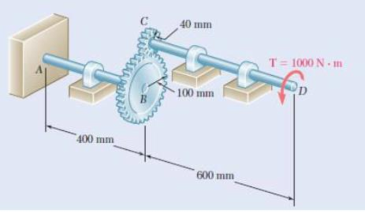
Chapter 3.3, Problem 48P
The design of the gear-and-shaft system shown requires that steel shafts of the same diameter be used for both AB and CD. It is further required that τmax ≤ 60 MPa and that the angle ϕD through which end D of shaft CD rotates not exceed 1.5°. Knowing that G = 77.2 GPa, determine the required diameter of the shafts.
Expert Solution & Answer
Want to see the full answer?
Check out a sample textbook solution
Students have asked these similar questions
state the formulas for calculating work done by gas
Exercises
Find the solution of the following Differential Equations
1) y" + y = 3x²
3)
"+2y+3y=27x
5) y"+y=6sin(x)
7) y"+4y+4y = 18 cosh(x)
9) (4)-5y"+4y = 10 cos(x)
11) y"+y=x²+x
13) y"-2y+y=e*
15) y+2y"-y'-2y=1-4x³
2) y"+2y' + y = x²
4) "+y=-30 sin(4x)
6) y"+4y+3y=sin(x)+2 cos(x)
8) y"-2y+2y= 2e* cos(x)
10) y+y-2y=3e*
12) y"-y=e*
14) y"+y+y=x+4x³ +12x²
16) y"-2y+2y=2e* cos(x)
The state of stress at a point is σ = -4.00 kpsi, σy = 16.00 kpsi, σ = -14.00 kpsi, Try = 11.00 kpsi,
Tyz = 8.000 kpsi, and T = -14.00 kpsi.
Determine the principal stresses.
The principal normal stress σ₁ is determined to be [
The principal normal stress σ2 is determined to be [
The principal normal stress σ3 is determined to be
kpsi.
kpsi.
The principal shear stress 71/2 is determined to be [
The principal shear stress 7½ is determined to be [
The principal shear stress T₁/, is determined to be [
kpsi.
kpsi.
kpsi.
kpsi.
Chapter 3 Solutions
EBK MECHANICS OF MATERIALS
Ch. 3.1 - Determine the torque T that causes a maximum...Ch. 3.1 - For the cylindrical shaft shown, determine the...Ch. 3.1 - (a) Determine the torque T that causes a maximum...Ch. 3.1 - (a) Determine the maximum shearing stress caused...Ch. 3.1 - (a) For the 3-in.-diameter solid cylinder and...Ch. 3.1 - Fig. P3.6 3.6 A torque T=3 kN m is applied to the...Ch. 3.1 - The solid spindle AB is made of a steel with an...Ch. 3.1 - The solid spindle AB has a diameter ds = 1.5 in....Ch. 3.1 - Fig. P3.9 and P3.10 3.10 The shafts of the pulley...Ch. 3.1 - Knowing that each of the shafts AB, BC, and CD...
Ch. 3.1 - Fig. P3.11 and P3.12 3.12 Knowing that an...Ch. 3.1 - Under normal operating conditions, the electric...Ch. 3.1 - In order to reduce the total mass of the assembly...Ch. 3.1 - The allowable shearing stress is 15 ksi in the...Ch. 3.1 - The allowable shearing stress is 15 ksi in the...Ch. 3.1 - The solid shaft shown is formed of a brass for...Ch. 3.1 - Solve Prob. 3.17 assuming that the direction of Tc...Ch. 3.1 - The solid rod AB has a diameter dAB= 60 mm and is...Ch. 3.1 - Fig. P3.19 and P3.20 3.20 The solid rod AB has a...Ch. 3.1 - A torque of magnitude T = 1000 N m is applied at D...Ch. 3.1 - Fig. P3.21 and P3.22 3.22 A torque of magnitude T...Ch. 3.1 - Under normal operating conditions a motor exerts a...Ch. 3.1 - Fig P3.23 and P3.24 3.24 Under normal operating...Ch. 3.1 - Prob. 25PCh. 3.1 - Fig. P3.25 and P3.26 3.26 The two solid shafts are...Ch. 3.1 - For the gear train shown, the diameters of the...Ch. 3.1 - Fig. P3.27 and P3.28 3.28 A torque T = 900 N m is...Ch. 3.1 - Fig. P3.29 3.29 While the exact distribution of...Ch. 3.1 - Fig. P3.30 3.30 (a) For a given allowable shearing...Ch. 3.3 - Determine the largest allowable diameter of a...Ch. 3.3 - The ship at A has just started to drill for oil on...Ch. 3.3 - (a) For the solid steel shaft shown, determine the...Ch. 3.3 - (a) For the aluminum pipe shown (G = 27 GPa),...Ch. 3.3 - The electric motor exerts a 500 N m-torque on the...Ch. 3.3 - The torques shown are exerted on pulleys and B....Ch. 3.3 - The aluminum rod BC (G = 26 GPa) is bonded to the...Ch. 3.3 - The aluminum rod AB (G = 27 GPa) is bonded to the...Ch. 3.3 - The solid spindle AB has a diameter ds = 1.75 in....Ch. 3.3 - Fig. p3.39 and p3.40 3.40 The solid spindle AB has...Ch. 3.3 - Two shafts, each of 78in. diameter, are connected...Ch. 3.3 - Two solid steel shafts each of 30-mm diameter, are...Ch. 3.3 - A coder F, used to record in digital form the...Ch. 3.3 - Fig. p3.43 3.44 For the gear train described in...Ch. 3.3 - The design specifications of a 1.2-m-long solid...Ch. 3.3 - 3.46 and 3.47 The solid cylindrical rod BC of...Ch. 3.3 - 3.46 and 3.47 The solid cylindrical rod BC of...Ch. 3.3 - The design of the gear-and-shaft system shown...Ch. 3.3 - The electric motor exerts a torque of 900 Nm on...Ch. 3.3 - A hole is punched at A in a plastic sheet by...Ch. 3.3 - The solid cylinders AB and BC are bonded together...Ch. 3.3 - Solve Prob. 3.51, assuming that cylinder AB is...Ch. 3.3 - The composite shaft shown consists of a...Ch. 3.3 - Fig. p3.53 and p3.54 3.54 The composite shaft...Ch. 3.3 - Two solid steel shafts (G = 77.2 GPa) are...Ch. 3.3 - Solve Prob. 3.55, assuming that the shaft AB is...Ch. 3.3 - 3.57 and 3.58 Two solid steel shafts are fitted...Ch. 3.3 - 3.57 and 3.58 Two solid steel shafts are fitted...Ch. 3.3 - The steel jacket CD has been attached to the...Ch. 3.3 - A torque T is applied as shown to a solid tapered...Ch. 3.3 - Prob. 61PCh. 3.3 - A solid shaft and a hollow shaft are made of the...Ch. 3.3 - An annular plate of thickness t and modulus G is...Ch. 3.5 - Determine the maximum shearing stress in a solid...Ch. 3.5 - Determine the maximum shearing stress in a solid...Ch. 3.5 - Using an allowable shearing stress of 4.5 ksi,...Ch. 3.5 - Using an allowable shearing stress of 50 MPa,...Ch. 3.5 - While a steel shaft of the cross section shown...Ch. 3.5 - Determine the required thickness of the 50-mm...Ch. 3.5 - A steel drive shaft is 6 ft long and its outer and...Ch. 3.5 - The hollow steel shaft shown (G = 77.2 GPa, all =...Ch. 3.5 - A steel pipe of 3.5-in. outer diameter is to be...Ch. 3.5 - 3.73 The design of a machine element calls for a...Ch. 3.5 - Three shafts and four gears are used to form a...Ch. 3.5 - Three shafts and four gears are used to form a...Ch. 3.5 - The two solid shafts and gears shown are used to...Ch. 3.5 - Fig. P3.76 and P3.77 3.77 The two solid shafts and...Ch. 3.5 - The shaft-disk-belt arrangement shown is used to...Ch. 3.5 - A 5-ft-long solid steel shaft of 0.875-in....Ch. 3.5 - A 2.5-m-long steel shaft of 30-mm diameter rotates...Ch. 3.5 - The design specifications of a 1.2-m-long solid...Ch. 3.5 - A 1.5-m-long tubular steel shaft (G = 77.2 GPa) of...Ch. 3.5 - Fig. P3.82 and P3.83 3.83 A 1.5-m-long tubular...Ch. 3.5 - The stepped shaft shown must transmit 40 kW at a...Ch. 3.5 - The stepped shaft shown rotates at 450 rpm....Ch. 3.5 - Knowing that the stepped shaft shown transmits a...Ch. 3.5 - The stepped shaft shown must rotate at a frequency...Ch. 3.5 - Fig. P3.87 and P3.88 3.88 The stepped shaft shown...Ch. 3.5 - A torque of magnitude T = 200 lbin. is applied to...Ch. 3.5 - Fig. P3.89, P3.90 and P3.91 3.90 In the stepped...Ch. 3.5 - In the stepped shaft shown, which has a full...Ch. 3.8 - The solid circular shaft shown is made of a steel...Ch. 3.8 - Prob. 93PCh. 3.8 - Prob. 94PCh. 3.8 - Prob. 95PCh. 3.8 - Fig. P3.95 and P3.96 3.96 The solid shaft shown is...Ch. 3.8 - It is observed that a straightened paper clip can...Ch. 3.8 - The solid shaft shown is made of a mild steel that...Ch. 3.8 - Prob. 99PCh. 3.8 - Prob. 100PCh. 3.8 - Prob. 101PCh. 3.8 - Prob. 102PCh. 3.8 - Prob. 103PCh. 3.8 - Prob. 104PCh. 3.8 - A solid circular rod is made of a material that is...Ch. 3.8 - Prob. 106PCh. 3.8 - Prob. 107PCh. 3.8 - Prob. 108PCh. 3.8 - Prob. 109PCh. 3.8 - Prob. 110PCh. 3.8 - Prob. 111PCh. 3.8 - A 50-mm diameter cylinder is made of a brass for...Ch. 3.8 - Prob. 113PCh. 3.8 - The solid circular drill rod AB is made of a steel...Ch. 3.8 - Prob. 115PCh. 3.8 - Prob. 116PCh. 3.8 - After the solid shaft of Prob. 3.116 has been...Ch. 3.8 - The hollow shaft shown is made of a steel that is...Ch. 3.8 - Prob. 119PCh. 3.8 - Prob. 120PCh. 3.10 - Determine the smallest allowable square cross...Ch. 3.10 - Prob. 122PCh. 3.10 - Using all = 70 MPa and G = 27 GPa, determine for...Ch. 3.10 - Prob. 124PCh. 3.10 - Determine the largest torque T that can be applied...Ch. 3.10 - Each of the two brass bars shown is subjected to a...Ch. 3.10 - Prob. 127PCh. 3.10 - Prob. 128PCh. 3.10 - Prob. 129PCh. 3.10 - Shafts A and B are made of the same material and...Ch. 3.10 - Prob. 131PCh. 3.10 - Shafts A and B are made of the same material and...Ch. 3.10 - Prob. 133PCh. 3.10 - Prob. 134PCh. 3.10 - Prob. 135PCh. 3.10 - A 36-kipin. torque is applied to a 10-ft-long...Ch. 3.10 - A 4-m-long steel member has a W310 60 cross...Ch. 3.10 - Prob. 138PCh. 3.10 - A 5-kipft torque is applied to a hollow aluminum...Ch. 3.10 - A torque T = 750 kNm is applied to the hollow...Ch. 3.10 - A 750-Nm torque is applied to a hollow shaft...Ch. 3.10 - 3.142 and 3.143 A hollow member having the cross...Ch. 3.10 - A hollow member having the cross section shown is...Ch. 3.10 - A 90-Nm torque is applied to a hollow shaft having...Ch. 3.10 - 3.145 and 3.146 A hollow member having the cross...Ch. 3.10 - 3.145 and 3.146 A hollow member having the cross...Ch. 3.10 - A cooling tube having the cross section shown is...Ch. 3.10 - A hollow cylindrical shaft was designed to have a...Ch. 3.10 - Equal torques are applied to thin-walled tubes of...Ch. 3.10 - A hollow cylindrical shaft of length L, mean...Ch. 3 - A steel pipe of 12-in. outer diameter is...Ch. 3 - A torque of magnitude T = 120 Nm is applied to...Ch. 3 - Fig. P3.152 3.153 Two solid shafts are connected...Ch. 3 - Prob. 154RPCh. 3 - Prob. 155RPCh. 3 - A torque of magnitude T = 4 kNm is applied at end...Ch. 3 - Ends A and D of the two solid steel shafts AB and...Ch. 3 - As the hollow steel shaft shown rotates at 180...Ch. 3 - Prob. 159RPCh. 3 - Prob. 160RPCh. 3 - Prob. 161RPCh. 3 - The shaft AB is made of a material that is...
Knowledge Booster


Learn more about
Need a deep-dive on the concept behind this application? Look no further. Learn more about this topic, mechanical-engineering and related others by exploring similar questions and additional content below.Similar questions
- Repeat Problem 28, except using a shaft that is rotatingand transmitting a torque of 150 N * m from the left bearing to the middle of the shaft. Also, there is a profile keyseat at the middle under the load. (I want to understand this problem)arrow_forwardProb 2. The material distorts into the dashed position shown. Determine the average normal strains &x, Ey and the shear strain Yxy at A, and the average normal strain along line BE. 50 mm B 200 mm 15 mm 30 mm D ΕΙ 50 mm x A 150 mm Farrow_forwardProb 3. The triangular plate is fixed at its base, and its apex A is given a horizontal displacement of 5 mm. Determine the shear strain, Yxy, at A. Prob 4. The triangular plate is fixed at its base, and its apex A is given a horizontal displacement of 5 mm. Determine the average normal strain & along the x axis. Prob 5. The triangular plate is fixed at its base, and its apex A is given a horizontal displacement of 5 mm. Determine the average normal strain &x along the x' axis. x' 45° 800 mm 45° 45% 800 mm 5 mmarrow_forward
- An airplane lands on the straight runaway, originally travelling at 110 ft/s when s = 0. If it is subjected to the decelerations shown, determine the time t' needed to stop the plane and construct the s -t graph for the motion. draw a graph and show all work step by steparrow_forwarddny dn-1y dn-1u dn-24 +a1 + + Any = bi +b₂- + +bnu. dtn dtn-1 dtn-1 dtn-2 a) Let be a root of the characteristic equation 1 sn+a1sn- + +an = : 0. Show that if u(t) = 0, the differential equation has the solution y(t) = e\t. b) Let к be a zero of the polynomial b(s) = b₁s-1+b2sn−2+ Show that if the input is u(t) equation that is identically zero. = .. +bn. ekt, then there is a solution to the differentialarrow_forwardB 60 ft WAB AB 30% : The crane's telescopic boom rotates with the angular velocity w = 0.06 rad/s and angular acceleration a = 0.07 rad/s². At the same instant, the boom is extending with a constant speed of 0.8 ft/s, measured relative to the boom. Determine the magnitude of the acceleration of point B at this instant.arrow_forward
- The motion of peg P is constrained by the lemniscate curved slot in OB and by the slotted arm OA. (Figure 1) If OA rotates counterclockwise with a constant angular velocity of 0 = 3 rad/s, determine the magnitude of the velocity of peg P at 0 = 30°. Express your answer to three significant figures and include the appropriate units. Determine the magnitude of the acceleration of peg P at 0 = 30°. Express your answer to three significant figures and include the appropriate units. 0 (4 cos 2 0)m² B Aarrow_forward5: The structure shown was designed to support a30-kN load. It consists of a boom AB with a 30 x 50-mmrectangular cross section and a rod BC with a 20-mm-diametercircular cross section. The boom and the rod are connected bya pin at B and are supported by pins and brackets at A and C,respectively.1. Calculate the normal stress in boom AB and rod BC,indicate if in tension or compression.2. Calculate the shear stress of pins at A, B and C.3. Calculate the bearing stresses at A in member AB,and in the bracket.arrow_forward4: The boom AC is a 4-in. square steel tube with a wallthickness of 0.25 in. The boom is supported by the 0.5-in.-diameter pinat A, and the 0.375-in.-diameter cable BC. The working stresses are 25ksi for the cable, 18 ksi for the boom, and 13.6 ksi for shear in the pin.Neglect the weight of the boom.1. Calculate the maximum value of P (kips) based on boom compression and the maximum value of P (kips) based on tension in the cable.2. Calculate the maximum value of P (kips) based on shear in pin.arrow_forward
- 3: A steel strut S serving as a brace for a boat hoist transmits a compressive force P = 54 kN to the deck of a pier as shown in Fig. STR-08. The strut has a hollow square cross section with a wall thickness t =12mm and the angle θ between the strut and the horizontal is 40°. A pin through the strut transmits the compressive force from the strut to two gusset plates G that are welded to the base plate B. Four anchor bolts fasten the base plate to the deck. The diameter of the pin is 20mm, the thickness of the gusset plates is 16mm, the thickness of the base plate is 8mm, and the diameter of the anchor bolts is 12mm. Disregard any friction between the base plate and the deck.1. Determine the shear stress in the pin, in MPa and the shear stress in the anchor bolts, in MPa.2. Determine the bearing stress in the strut holes, in MPa.arrow_forward1. In the figure, the beam, W410x67, with 9 mm web thicknesssubjects the girder, W530x109 with 12 mm web thickness to a shear load,P (kN). 2L – 90 mm × 90 mm × 6 mm with bolts frame the beam to thegirder.Given: S1 = S2 = S5 = 40 mm; S3 = 75 mm; S4 = 110 mmAllowable Stresses are as follows:Bolt shear stress, Fv = 125 MPaBolt bearing stress, Fp = 510 MPa1. Determine the allowable load, P (kN), based on the shearcapacity of the 4 – 25 mm diameter bolts (4 – d1) and calculate the allowable load, P (kN), based on bolt bearing stress on the web of the beam.2. If P = 450 kN, determine the minimum diameter (mm) of 4 – d1based on allowable bolt shear stress and bearing stress of thebeam web.arrow_forward6: The 6-kN load P is supported by two wooden members of 75 x 125-mm uniform cross section that are joined by the simple glued scarf splice shown.1. Calculate the normal stress in the glue, in MPa.2. Calculate the shear stress in the glue, in MPa.arrow_forward
arrow_back_ios
SEE MORE QUESTIONS
arrow_forward_ios
Recommended textbooks for you
 Elements Of ElectromagneticsMechanical EngineeringISBN:9780190698614Author:Sadiku, Matthew N. O.Publisher:Oxford University Press
 Mechanics of Materials (10th Edition)Mechanical EngineeringISBN:9780134319650Author:Russell C. HibbelerPublisher:PEARSON
 Thermodynamics: An Engineering ApproachMechanical EngineeringISBN:9781259822674Author:Yunus A. Cengel Dr., Michael A. BolesPublisher:McGraw-Hill Education
 Control Systems EngineeringMechanical EngineeringISBN:9781118170519Author:Norman S. NisePublisher:WILEY
 Mechanics of Materials (MindTap Course List)Mechanical EngineeringISBN:9781337093347Author:Barry J. Goodno, James M. GerePublisher:Cengage Learning
 Engineering Mechanics: StaticsMechanical EngineeringISBN:9781118807330Author:James L. Meriam, L. G. Kraige, J. N. BoltonPublisher:WILEY
Elements Of Electromagnetics
Mechanical Engineering
ISBN:9780190698614
Author:Sadiku, Matthew N. O.
Publisher:Oxford University Press
Mechanics of Materials (10th Edition)
Mechanical Engineering
ISBN:9780134319650
Author:Russell C. Hibbeler
Publisher:PEARSON
Thermodynamics: An Engineering Approach
Mechanical Engineering
ISBN:9781259822674
Author:Yunus A. Cengel Dr., Michael A. Boles
Publisher:McGraw-Hill Education
Control Systems Engineering
Mechanical Engineering
ISBN:9781118170519
Author:Norman S. Nise
Publisher:WILEY
Mechanics of Materials (MindTap Course List)
Mechanical Engineering
ISBN:9781337093347
Author:Barry J. Goodno, James M. Gere
Publisher:Cengage Learning
Engineering Mechanics: Statics
Mechanical Engineering
ISBN:9781118807330
Author:James L. Meriam, L. G. Kraige, J. N. Bolton
Publisher:WILEY
Power Transmission; Author: Terry Brown Mechanical Engineering;https://www.youtube.com/watch?v=YVm4LNVp1vA;License: Standard Youtube License