
EBK MECHANICS OF MATERIALS
7th Edition
ISBN: 9780100257061
Author: BEER
Publisher: YUZU
expand_more
expand_more
format_list_bulleted
Concept explainers
Videos
Textbook Question
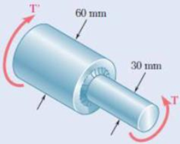
Chapter 3.5, Problem 87P
The stepped shaft shown must rotate at a frequency of 50 Hz. Knowing that the radius of the fillet is r = 8 mm and the allowable shearing stress is 45 MPa, determine the maximum power that can be transmitted.
Expert Solution & Answer
Want to see the full answer?
Check out a sample textbook solution
Students have asked these similar questions
2. Figure 2 shows a device for lifting bricks and concrete blocks. It comprises two compo-
nents ABC and BD, with a frictionless pin at B. Determine the minimum coefficient of friction
required at A and D if the device is to work satisfactorily.
W
all dimensions in inches
Figure 2
D
1. The shaft AD in Figure 1 supports two pulleys at B and C of radius 200 mm and 250 mm
respectively. The shaft is supported in frictionless bearings at A and D and is rotating clockwise
(when viewed from the right) at a constant speed of 300 rpm. Only bearing A can support thrust.
The tensions T₁ = 200 N, T₂ = 400 N, and T3 = 300 N. The distances AB = 120 mm, BC = 150
mm, and CD120 mm. Find the tension 74 and the reaction forces at the bearings.
A
T
fo
Figure 1
5. Figure 5 shows a two-dimensional idealization of the front suspension system for a car.
During cornering, the road exerts a vertical force of 5 kN and a leftward horizontal force of 1.2
kN on the tire, which is of 510 mm diameter. Draw free-body diagrams of each component and
determine the forces transmitted between them.
250
A
-320
B
170
D
170
-220-220-
all dimensions in mm.
Figure 5
Chapter 3 Solutions
EBK MECHANICS OF MATERIALS
Ch. 3.1 - Determine the torque T that causes a maximum...Ch. 3.1 - For the cylindrical shaft shown, determine the...Ch. 3.1 - (a) Determine the torque T that causes a maximum...Ch. 3.1 - (a) Determine the maximum shearing stress caused...Ch. 3.1 - (a) For the 3-in.-diameter solid cylinder and...Ch. 3.1 - Fig. P3.6 3.6 A torque T=3 kN m is applied to the...Ch. 3.1 - The solid spindle AB is made of a steel with an...Ch. 3.1 - The solid spindle AB has a diameter ds = 1.5 in....Ch. 3.1 - Fig. P3.9 and P3.10 3.10 The shafts of the pulley...Ch. 3.1 - Knowing that each of the shafts AB, BC, and CD...
Ch. 3.1 - Fig. P3.11 and P3.12 3.12 Knowing that an...Ch. 3.1 - Under normal operating conditions, the electric...Ch. 3.1 - In order to reduce the total mass of the assembly...Ch. 3.1 - The allowable shearing stress is 15 ksi in the...Ch. 3.1 - The allowable shearing stress is 15 ksi in the...Ch. 3.1 - The solid shaft shown is formed of a brass for...Ch. 3.1 - Solve Prob. 3.17 assuming that the direction of Tc...Ch. 3.1 - The solid rod AB has a diameter dAB= 60 mm and is...Ch. 3.1 - Fig. P3.19 and P3.20 3.20 The solid rod AB has a...Ch. 3.1 - A torque of magnitude T = 1000 N m is applied at D...Ch. 3.1 - Fig. P3.21 and P3.22 3.22 A torque of magnitude T...Ch. 3.1 - Under normal operating conditions a motor exerts a...Ch. 3.1 - Fig P3.23 and P3.24 3.24 Under normal operating...Ch. 3.1 - Prob. 25PCh. 3.1 - Fig. P3.25 and P3.26 3.26 The two solid shafts are...Ch. 3.1 - For the gear train shown, the diameters of the...Ch. 3.1 - Fig. P3.27 and P3.28 3.28 A torque T = 900 N m is...Ch. 3.1 - Fig. P3.29 3.29 While the exact distribution of...Ch. 3.1 - Fig. P3.30 3.30 (a) For a given allowable shearing...Ch. 3.3 - Determine the largest allowable diameter of a...Ch. 3.3 - The ship at A has just started to drill for oil on...Ch. 3.3 - (a) For the solid steel shaft shown, determine the...Ch. 3.3 - (a) For the aluminum pipe shown (G = 27 GPa),...Ch. 3.3 - The electric motor exerts a 500 N m-torque on the...Ch. 3.3 - The torques shown are exerted on pulleys and B....Ch. 3.3 - The aluminum rod BC (G = 26 GPa) is bonded to the...Ch. 3.3 - The aluminum rod AB (G = 27 GPa) is bonded to the...Ch. 3.3 - The solid spindle AB has a diameter ds = 1.75 in....Ch. 3.3 - Fig. p3.39 and p3.40 3.40 The solid spindle AB has...Ch. 3.3 - Two shafts, each of 78in. diameter, are connected...Ch. 3.3 - Two solid steel shafts each of 30-mm diameter, are...Ch. 3.3 - A coder F, used to record in digital form the...Ch. 3.3 - Fig. p3.43 3.44 For the gear train described in...Ch. 3.3 - The design specifications of a 1.2-m-long solid...Ch. 3.3 - 3.46 and 3.47 The solid cylindrical rod BC of...Ch. 3.3 - 3.46 and 3.47 The solid cylindrical rod BC of...Ch. 3.3 - The design of the gear-and-shaft system shown...Ch. 3.3 - The electric motor exerts a torque of 900 Nm on...Ch. 3.3 - A hole is punched at A in a plastic sheet by...Ch. 3.3 - The solid cylinders AB and BC are bonded together...Ch. 3.3 - Solve Prob. 3.51, assuming that cylinder AB is...Ch. 3.3 - The composite shaft shown consists of a...Ch. 3.3 - Fig. p3.53 and p3.54 3.54 The composite shaft...Ch. 3.3 - Two solid steel shafts (G = 77.2 GPa) are...Ch. 3.3 - Solve Prob. 3.55, assuming that the shaft AB is...Ch. 3.3 - 3.57 and 3.58 Two solid steel shafts are fitted...Ch. 3.3 - 3.57 and 3.58 Two solid steel shafts are fitted...Ch. 3.3 - The steel jacket CD has been attached to the...Ch. 3.3 - A torque T is applied as shown to a solid tapered...Ch. 3.3 - Prob. 61PCh. 3.3 - A solid shaft and a hollow shaft are made of the...Ch. 3.3 - An annular plate of thickness t and modulus G is...Ch. 3.5 - Determine the maximum shearing stress in a solid...Ch. 3.5 - Determine the maximum shearing stress in a solid...Ch. 3.5 - Using an allowable shearing stress of 4.5 ksi,...Ch. 3.5 - Using an allowable shearing stress of 50 MPa,...Ch. 3.5 - While a steel shaft of the cross section shown...Ch. 3.5 - Determine the required thickness of the 50-mm...Ch. 3.5 - A steel drive shaft is 6 ft long and its outer and...Ch. 3.5 - The hollow steel shaft shown (G = 77.2 GPa, all =...Ch. 3.5 - A steel pipe of 3.5-in. outer diameter is to be...Ch. 3.5 - 3.73 The design of a machine element calls for a...Ch. 3.5 - Three shafts and four gears are used to form a...Ch. 3.5 - Three shafts and four gears are used to form a...Ch. 3.5 - The two solid shafts and gears shown are used to...Ch. 3.5 - Fig. P3.76 and P3.77 3.77 The two solid shafts and...Ch. 3.5 - The shaft-disk-belt arrangement shown is used to...Ch. 3.5 - A 5-ft-long solid steel shaft of 0.875-in....Ch. 3.5 - A 2.5-m-long steel shaft of 30-mm diameter rotates...Ch. 3.5 - The design specifications of a 1.2-m-long solid...Ch. 3.5 - A 1.5-m-long tubular steel shaft (G = 77.2 GPa) of...Ch. 3.5 - Fig. P3.82 and P3.83 3.83 A 1.5-m-long tubular...Ch. 3.5 - The stepped shaft shown must transmit 40 kW at a...Ch. 3.5 - The stepped shaft shown rotates at 450 rpm....Ch. 3.5 - Knowing that the stepped shaft shown transmits a...Ch. 3.5 - The stepped shaft shown must rotate at a frequency...Ch. 3.5 - Fig. P3.87 and P3.88 3.88 The stepped shaft shown...Ch. 3.5 - A torque of magnitude T = 200 lbin. is applied to...Ch. 3.5 - Fig. P3.89, P3.90 and P3.91 3.90 In the stepped...Ch. 3.5 - In the stepped shaft shown, which has a full...Ch. 3.8 - The solid circular shaft shown is made of a steel...Ch. 3.8 - Prob. 93PCh. 3.8 - Prob. 94PCh. 3.8 - Prob. 95PCh. 3.8 - Fig. P3.95 and P3.96 3.96 The solid shaft shown is...Ch. 3.8 - It is observed that a straightened paper clip can...Ch. 3.8 - The solid shaft shown is made of a mild steel that...Ch. 3.8 - Prob. 99PCh. 3.8 - Prob. 100PCh. 3.8 - Prob. 101PCh. 3.8 - Prob. 102PCh. 3.8 - Prob. 103PCh. 3.8 - Prob. 104PCh. 3.8 - A solid circular rod is made of a material that is...Ch. 3.8 - Prob. 106PCh. 3.8 - Prob. 107PCh. 3.8 - Prob. 108PCh. 3.8 - Prob. 109PCh. 3.8 - Prob. 110PCh. 3.8 - Prob. 111PCh. 3.8 - A 50-mm diameter cylinder is made of a brass for...Ch. 3.8 - Prob. 113PCh. 3.8 - The solid circular drill rod AB is made of a steel...Ch. 3.8 - Prob. 115PCh. 3.8 - Prob. 116PCh. 3.8 - After the solid shaft of Prob. 3.116 has been...Ch. 3.8 - The hollow shaft shown is made of a steel that is...Ch. 3.8 - Prob. 119PCh. 3.8 - Prob. 120PCh. 3.10 - Determine the smallest allowable square cross...Ch. 3.10 - Prob. 122PCh. 3.10 - Using all = 70 MPa and G = 27 GPa, determine for...Ch. 3.10 - Prob. 124PCh. 3.10 - Determine the largest torque T that can be applied...Ch. 3.10 - Each of the two brass bars shown is subjected to a...Ch. 3.10 - Prob. 127PCh. 3.10 - Prob. 128PCh. 3.10 - Prob. 129PCh. 3.10 - Shafts A and B are made of the same material and...Ch. 3.10 - Prob. 131PCh. 3.10 - Shafts A and B are made of the same material and...Ch. 3.10 - Prob. 133PCh. 3.10 - Prob. 134PCh. 3.10 - Prob. 135PCh. 3.10 - A 36-kipin. torque is applied to a 10-ft-long...Ch. 3.10 - A 4-m-long steel member has a W310 60 cross...Ch. 3.10 - Prob. 138PCh. 3.10 - A 5-kipft torque is applied to a hollow aluminum...Ch. 3.10 - A torque T = 750 kNm is applied to the hollow...Ch. 3.10 - A 750-Nm torque is applied to a hollow shaft...Ch. 3.10 - 3.142 and 3.143 A hollow member having the cross...Ch. 3.10 - A hollow member having the cross section shown is...Ch. 3.10 - A 90-Nm torque is applied to a hollow shaft having...Ch. 3.10 - 3.145 and 3.146 A hollow member having the cross...Ch. 3.10 - 3.145 and 3.146 A hollow member having the cross...Ch. 3.10 - A cooling tube having the cross section shown is...Ch. 3.10 - A hollow cylindrical shaft was designed to have a...Ch. 3.10 - Equal torques are applied to thin-walled tubes of...Ch. 3.10 - A hollow cylindrical shaft of length L, mean...Ch. 3 - A steel pipe of 12-in. outer diameter is...Ch. 3 - A torque of magnitude T = 120 Nm is applied to...Ch. 3 - Fig. P3.152 3.153 Two solid shafts are connected...Ch. 3 - Prob. 154RPCh. 3 - Prob. 155RPCh. 3 - A torque of magnitude T = 4 kNm is applied at end...Ch. 3 - Ends A and D of the two solid steel shafts AB and...Ch. 3 - As the hollow steel shaft shown rotates at 180...Ch. 3 - Prob. 159RPCh. 3 - Prob. 160RPCh. 3 - Prob. 161RPCh. 3 - The shaft AB is made of a material that is...
Knowledge Booster


Learn more about
Need a deep-dive on the concept behind this application? Look no further. Learn more about this topic, mechanical-engineering and related others by exploring similar questions and additional content below.Similar questions
- 8. The force F in Figure 8 is 120 lb and the angle 0 = 25°. Find the axial force N, the shear force V and the bending moment M at the point K which is midway between B and C and illustrate their directions on a sketch of the segment KCD. E -0 B K అ D H 7 A- all dimensions in inches Figure 8 Ꮎ G Farrow_forward6. Determine the coordinates x, y of the centroid of the area shaded in Figure 6. y y=x³ Figure 6 3arrow_forward3. Use the method of sections to determine the forces in the members BD, CD, CE in the struc- ture of Figure 3. A B D 4 kN 6 kN all dimensions in meters. Figure 3arrow_forward
- A pipeline engineer is considering alternative natural gas pipeline routings. The first route is mostly over land and the second is primarily undersea. Both pipelines will need some valve and fitting replacements in year 25. Cost data for each route is shown in Table P2.21. Notice that the undersea route has a higher initial cost due to higher installation costs and extra corrosion protection for the pipeline. However, the undersea route has cheaper security and maintenance costs which substantially reduces annual costs. The MARR for the project is 15%. Determine which route should be pursued based on a present worth analysis.arrow_forwardThe state of stress at a point is σ = -4.00 kpsi, σy Tyz = 8.000 kpsi, and T₂ = -14.00 kpsi. What is the maximum shear stress for this case? The maximum shear stress is kpsi. = 16.00 kpsi, σ = -14.00 kpsi, Try = 11.00 kpsi,arrow_forwardThe initial cost of a proposed heat recovery system is $375,000. The annual operation andmaintenance costs are projected to be $12,000. The salvage value of the system at the end of itsuseful life (projected to be 30 years) is $60,000. The annual savings in fuel costs resulting fromthis system are estimated to be $55,000 per year.a. Assuming annual compounding, determine the rate of return for this heat recovery system.b. If management has set the MARR to be 15% for a heat recovery system like this, what is themaximum initial cost that can be spent on the system (assuming that all other costs and incomesare the same)?arrow_forward
- The initial cost of a machine for a production facility is $225,000. The machine is expected tolast for 10 years with no salvage value. The company’s tax rate is 49% and SLD is used todepreciate the machine. For this type of depreciation, the tax life of the machine is considered 8years and its salvage value is $5,000. The after-tax rate of return is 14.3%. Determine the uniformannual before-tax cash flow.arrow_forwardThree alternatives are being considered for an air cleaning system. All three systems have a lifeof 10 years with no salvage value. System A has an initial cost of $29,000. During the first fiveyears of operation, the annual costs to operate system A are $5,000. During the second five years,the annual cost of system A increases to $16,000. System B has an initial cost of $43,000. Theannual cost to operate system B is $4,000, however, after the first year, this cost increases by$1,600 per year. System C has an initial cost of $58,000 with an annual cost of $2,400. System Crequires two upgrades: one during year 4 which costs $6,000, and the other during year 8 whichcosts $3,000. The MARR for this project is 17%. Determine which air cleaning system should beinstalled based on an economic analysis.arrow_forwardShow all work as much as you can and box out answersarrow_forward
- Show as much work as possible and box out answers pleasearrow_forwardon-the-job conditions. 9 ±0.2- 0.5 M Application questions 1-7 refer to the drawing above. 1. What does the flatness tolerance labeled "G" apply to? Surface F A. B. Surfaces E and F C. Surfaces D, E, H, and I D. The derived median plane of 12 +0.2 0.5 0.5 CF) 20 ±0.2 0.1 7. O 12 ±0.2- H 0.3 ASME Y14.5-2009arrow_forwardelements, each with a length of 1 m. Determine the temperature on node 1, 2, 3, 4. 3. Solve the strong form analytically (you may choose Maple, MATLAB or Mathematica to help you solve this ODE). Compare the FE approximate temperature distribution through the block against the analytical solution. 1 (1) 200 °C 2 (2) 3 m 3 (3)arrow_forward
arrow_back_ios
SEE MORE QUESTIONS
arrow_forward_ios
Recommended textbooks for you
 Elements Of ElectromagneticsMechanical EngineeringISBN:9780190698614Author:Sadiku, Matthew N. O.Publisher:Oxford University Press
 Mechanics of Materials (10th Edition)Mechanical EngineeringISBN:9780134319650Author:Russell C. HibbelerPublisher:PEARSON
 Thermodynamics: An Engineering ApproachMechanical EngineeringISBN:9781259822674Author:Yunus A. Cengel Dr., Michael A. BolesPublisher:McGraw-Hill Education
 Control Systems EngineeringMechanical EngineeringISBN:9781118170519Author:Norman S. NisePublisher:WILEY
 Mechanics of Materials (MindTap Course List)Mechanical EngineeringISBN:9781337093347Author:Barry J. Goodno, James M. GerePublisher:Cengage Learning
 Engineering Mechanics: StaticsMechanical EngineeringISBN:9781118807330Author:James L. Meriam, L. G. Kraige, J. N. BoltonPublisher:WILEY
Elements Of Electromagnetics
Mechanical Engineering
ISBN:9780190698614
Author:Sadiku, Matthew N. O.
Publisher:Oxford University Press
Mechanics of Materials (10th Edition)
Mechanical Engineering
ISBN:9780134319650
Author:Russell C. Hibbeler
Publisher:PEARSON
Thermodynamics: An Engineering Approach
Mechanical Engineering
ISBN:9781259822674
Author:Yunus A. Cengel Dr., Michael A. Boles
Publisher:McGraw-Hill Education
Control Systems Engineering
Mechanical Engineering
ISBN:9781118170519
Author:Norman S. Nise
Publisher:WILEY
Mechanics of Materials (MindTap Course List)
Mechanical Engineering
ISBN:9781337093347
Author:Barry J. Goodno, James M. Gere
Publisher:Cengage Learning
Engineering Mechanics: Statics
Mechanical Engineering
ISBN:9781118807330
Author:James L. Meriam, L. G. Kraige, J. N. Bolton
Publisher:WILEY
Everything About COMBINED LOADING in 10 Minutes! Mechanics of Materials; Author: Less Boring Lectures;https://www.youtube.com/watch?v=N-PlI900hSg;License: Standard youtube license