Concept explainers
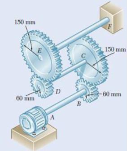
Three shafts and four gears are used to form a gear train that will transmit power from the motor at A to a machine tool at F. (Bearings for the shafts are omitted in the sketch.) The diameter of each shaft is as follows: dAB = 16mm, dCD = 20 mm, dEF = 28 mm. Knowing that the frequency of the motor is 24 Hz and that the allowable shearing stress for each shaft is 75 MPa, determine the maximum power that can be transmitted.

The maximum power that can be transmitted by shaft.
Answer to Problem 74P
The maximum power that can be transmitted by the shaft is
Explanation of Solution
Given information:
The frequency of the motor is 24 Hz.
The allowable shearing stress in each shaft is 75 MPa.
The diameter of the shaft AB is
The diameter of the shaft CD is
The diameter of the shaft EF is
Calculation:
The maximum shear stress in the shaft
Here, T is the torque transmitted by the shaft, c is the radius of the shaft, and J is the polar moment of inertia of the shaft.
The power transmitted by the shaft
For shaft AB:
The polar moment of inertia of shaft AB with radius
Substitute 75 MPa for
The frequency of the shaft AB is
Substitute
For shaft CD:
The polar moment of inertia of shaft CD with radius
Substitute 75 MPa for
The radius at gear B is
The radius at gear C is
The frequency of the shaft CD is,
Substitute
For shaft EF:
The polar moment of inertia of shaft EF with radius
Substitute 75 MPa for
The radius at gear D is
The radius at gear E is
The frequency of the shaft EF is,
Substitute
The maximum allowable power is the smallest value calculated among the shafts AB, CD, and EF.
The allowable power
Therefore, the maximum power that can be transmitted by the shaft is
Want to see more full solutions like this?
Chapter 3 Solutions
EBK MECHANICS OF MATERIALS
- A piston-cylinder device contains 0.87 kg of refrigerant-134a at -10°C. The piston that is free to move has a mass of 12 kg and a diameter of 25 cm. The local atmospheric pressure is 88 kPa. Now, heat is transferred to refrigerant-134a until the temperature is 15°C. Use data from the tables. R-134a -10°C Determine the final pressure of the refrigerant-134a. The final pressure is kPa.arrow_forwardThe hydraulic cylinder BC exerts on member AB a force P directed along line BC. The force P must have a 560-N component perpendicular to member AB. A M 45° 30° C Determine the force component along line AB. The force component along line AB is N.arrow_forward! Required information A telephone cable is clamped at A to the pole AB. The tension in the left-hand portion of the cable is given to be T₁ = 815 lb. A 15° 25° B T₂ Using trigonometry, determine the required tension T₂ in the right-hand portion if the resultant R of the forces exerted by the cable at A is to be vertical. The required tension is lb.arrow_forward
- What are examples of at least three (3) applications of tolerance fitting analysis.arrow_forwardThe primary material used in the production of glass products is silica sand. True or Falsearrow_forwardWhich one of the following is the most common polymer type in fiber-reinforced polymer composites? thermosets thermoplastics elastomers none of the abovearrow_forward
- Thermoset polymers can be recycled with little to no degradation in properties. True or Falsearrow_forwardTwo forces are applied as shown to a hook support. The magnitude of P is 38 N. 50 N 25° DG a 터 Using trigonometry, determine the required angle a such that the resultant R of the two forces applied to the support will be horizontal. The value of a isarrow_forwardNo chatgpt pls will upvotearrow_forward
 Elements Of ElectromagneticsMechanical EngineeringISBN:9780190698614Author:Sadiku, Matthew N. O.Publisher:Oxford University Press
 Mechanics of Materials (10th Edition)Mechanical EngineeringISBN:9780134319650Author:Russell C. HibbelerPublisher:PEARSON
 Thermodynamics: An Engineering ApproachMechanical EngineeringISBN:9781259822674Author:Yunus A. Cengel Dr., Michael A. BolesPublisher:McGraw-Hill Education
 Control Systems EngineeringMechanical EngineeringISBN:9781118170519Author:Norman S. NisePublisher:WILEY
 Mechanics of Materials (MindTap Course List)Mechanical EngineeringISBN:9781337093347Author:Barry J. Goodno, James M. GerePublisher:Cengage Learning
 Engineering Mechanics: StaticsMechanical EngineeringISBN:9781118807330Author:James L. Meriam, L. G. Kraige, J. N. BoltonPublisher:WILEY


