
Power System Analysis & Design
6th Edition
ISBN: 9781305636187
Author: Glover, J. Duncan, Overbye, Thomas J. (thomas Jeffrey), Sarma, Mulukutla S.
Publisher: Cengage Learning,
expand_more
expand_more
format_list_bulleted
Concept explainers
Videos
Textbook Question
Chapter 3, Problem 3.48P
With the same transformer banks as in Problem 3.47, Figure 3.41 shows the oneline diagram of a generator, a step-up transformer bank, a transmission line, a stepown transformer bank, and an impedan load. The generator terminal voltage is 15 kV (line-to-line).
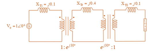
(a) Draw the per-phase equivalent circuit, aounting for phase shifts for positive-sequence operation.
(b) By choosing the line-to-neutral generator terminal voltage as the reference, determine the magnitudes of the generator current, transmiss ion-line current, load current, and line-to-line load voltage. Also, find the three-phase complex power delivered to the load.
Expert Solution & Answer
Want to see the full answer?
Check out a sample textbook solution
Students have asked these similar questions
Solve by Pen and Paper not using chatgpt
f. The figure below shows two stage RC coupled amplifier. If the input resistance Rin
of each stage is 1kN. (B = 100). Determine its overall voltage gain. (5 marks)
+15V
ΣΚΩ
kn
10kΩ
10ΚΩ
output
35 ΚΩ
2ΚΩ
5kЛ
2ΚΩ
NO AI PLEASE
Chapter 3 Solutions
Power System Analysis & Design
Ch. 3 - The Ohms law for the magnetic circuit states that...Ch. 3 - For an ideal transformer, the efficiency is (a) 0...Ch. 3 - For an ideal 2-winding transformer, the...Ch. 3 - An ideal transformer has no real or reactive power...Ch. 3 - For an ideal 2-winding transformer, an impedance...Ch. 3 - Consider Figure 3.4. For an ideal phase-shifting...Ch. 3 - Consider Figure 3.5. Match the following, those on...Ch. 3 - The units of admittance, conductance, and...Ch. 3 - Match the following: (i) Hysteresis loss (a) Can...Ch. 3 - For large power transformers rated more than 500...
Ch. 3 - For a short-circuit test on a 2-winding...Ch. 3 - The per-unit quantity is always dimensionless. (a)...Ch. 3 - Consider the adopted per-unit system for the...Ch. 3 - The ideal transformer windings are eliminated from...Ch. 3 - To convert a per-unit impedance from old to new...Ch. 3 - In developing per-unit circuits of systems such as...Ch. 3 - Prob. 3.17MCQCh. 3 - Prob. 3.18MCQCh. 3 - With the American Standard notation, in either a...Ch. 3 - Prob. 3.20MCQCh. 3 - In order to avoid difficulties with third-harmonic...Ch. 3 - Does an open connection permit balanced...Ch. 3 - Does an open- operation, the kVA rating compared...Ch. 3 - It is stated that (i) balanced three-phase...Ch. 3 - In developing per-unit equivalent circuits for...Ch. 3 - In per-unit equivalent circuits of practical...Ch. 3 - Prob. 3.27MCQCh. 3 - Prob. 3.28MCQCh. 3 - For developing per-unit equivalent circuits of...Ch. 3 - Prob. 3.30MCQCh. 3 - Prob. 3.31MCQCh. 3 - Prob. 3.32MCQCh. 3 - The direct electrical connection of the windings...Ch. 3 - Consider Figure 3.25 of the text for a transformer...Ch. 3 - (a) An ideal single-phase two-winding transformer...Ch. 3 - An ideal transformer with N1=1000andN2=250 is...Ch. 3 - Consider an ideal transformer with...Ch. 3 - A single-phase 100-kVA,2400/240-volt,60-Hz...Ch. 3 - Prob. 3.5PCh. 3 - Prob. 3.6PCh. 3 - Consider a source of voltage v(t)=102sin(2t)V,...Ch. 3 - Prob. 3.8PCh. 3 - Prob. 3.9PCh. 3 - A single-phase step-down transformer is rated...Ch. 3 - For the transformer in Problem 3.10. The...Ch. 3 - Prob. 3.12PCh. 3 - A single-phase 50-kVA,2400/240-volt,60-Hz...Ch. 3 - A single-phase 50-kVA,2400/240-volt,60-Hz...Ch. 3 - Rework Problem 3.14 if the transformer is...Ch. 3 - A single-phase, 50-kVA,2400/240-V,60-Hz...Ch. 3 - The transformer of Problem 3.16 is supplying a...Ch. 3 - Using the transformer ratings as base quantities,...Ch. 3 - Using the transformer ratings as base quantities....Ch. 3 - Using base values of 20 kVA and 115 volts in zone...Ch. 3 - Prob. 3.21PCh. 3 - A balanced Y-connected voltage source with...Ch. 3 - Figure 3.32 shows the oneline diagram of a...Ch. 3 - For Problem 3.18, the motor operates at full load,...Ch. 3 - Consider a single-phase electric system shown in...Ch. 3 - A bank of three single-phase transformers, each...Ch. 3 - A three-phase transformer is rated...Ch. 3 - For the system shown in Figure 3.34. draw an...Ch. 3 - Consider three ideal single-phase transformers...Ch. 3 - Reconsider Problem 3.29. If Va,VbandVc are a...Ch. 3 - Prob. 3.31PCh. 3 - Determine the positive- and negative-sequence...Ch. 3 - Consider the three single-phase two-winding...Ch. 3 - Three single-phase, two-winding transformers, each...Ch. 3 - Consider a bank of this single-phase two-winding...Ch. 3 - Three single-phase two-winding transformers, each...Ch. 3 - Three single-phase two-winding transformers, each...Ch. 3 - Consider a three-phase generator rated...Ch. 3 - The leakage reactance of a three-phase,...Ch. 3 - Prob. 3.40PCh. 3 - Consider the single-line diagram of the power...Ch. 3 - For the power system in Problem 3.41, the...Ch. 3 - Three single-phase transformers, each rated...Ch. 3 - A 130-MVA,13.2-kV three-phase generator, which has...Ch. 3 - Figure 3.39 shows a oneline diagram of a system in...Ch. 3 - The motors M1andM2 of Problem 3.45 have inputs of...Ch. 3 - Consider the oneline diagram shown in Figure 3.40....Ch. 3 - With the same transformer banks as in Problem...Ch. 3 - Consider the single-Line diagram of a power system...Ch. 3 - A single-phase three-winding transformer has the...Ch. 3 - The ratings of a three-phase three-winding...Ch. 3 - Prob. 3.52PCh. 3 - The ratings of a three-phase, three-winding...Ch. 3 - An infinite bus, which is a constant voltage...Ch. 3 - A single-phase l0-kVA,2300/230-volt,60-Hz...Ch. 3 - Three single-phase two-winding transformers, each...Ch. 3 - A two-winding single-phase transformer rated...Ch. 3 - A single-phase two-winding transformer rated...Ch. 3 - Prob. 3.59PCh. 3 - PowerWorid Simulator case Problem 3_60 duplicates...Ch. 3 - Rework Example 3.12 for a+10 tap, providing a 10...Ch. 3 - A 23/230-kV step-up transformer feeds a...Ch. 3 - The per-unit equivalent circuit of two...Ch. 3 - Reconsider Problem 3.64 with the change that now...Ch. 3 - What are the advantages of correctly specifying a...Ch. 3 - Why is it important to reduce the moisture within...Ch. 3 - What should be the focus of transformer preventive...
Knowledge Booster


Learn more about
Need a deep-dive on the concept behind this application? Look no further. Learn more about this topic, electrical-engineering and related others by exploring similar questions and additional content below.Similar questions
- solve by impedancearrow_forwardConsider the circuit diagram below. Compute a single equivalent impedance for this circuit for a source frequency of F = 60 Hz. Express your final answer as a complex impedance with rectangular coordinates. You must show your all your work for the complex math. Include a diagram of the equivalent circuit as part of your solution.arrow_forwardConsider the circuit diagram below. Compute a single equivalent impedance for this circuit for a source frequency of f = 165 Hz. Express your final answer as a phasor with polar coordinates. You must show your all your work for the complex math. Include a diagram of the equivalent circuit as part of your solution.arrow_forward
- Consider the circuit diagram below. Using mesh analysis, compute the currents (a) IR1, (b) IL1, and (c) IC1. Express your final answers as phasors using polar coordinates with phase angles measured in degrees. Your solution should include the circuit diagram redrawn to indicate these currents and their directions. You must solve the system of equations using MATLAB and include the code or commands you ran as part of your solution.arrow_forwarduse kvl to solvearrow_forwardR1 is 978 ohms R2 is 2150 ohms R3 is 4780 R1 is parallel to R2 and R2 is parallel to R3 and R1 and R3 are in seriesarrow_forward
- Q7 For the circuit shown in Fig. 2.20, the transistors are identical and have the following parameters: hfe = 50, hie = 1.1K, hre = 0, and hoe = 0. Calculate Auf, Rif and Rof. Ans: 45.4; 112 KQ; 129. 25 V 10k 47k 4.7k Vo 150k w Vs 47k 4.7k W 22 5μF 33k 50uF 50μF 4.7k 4.7k R₁ Rof Rif R1000 Fig. 2.20 Circuit for Q7.arrow_forwardQ6)) The transistors in the feedback amplifier shown are identical, and their h-parameters are.. hie = 1.1k, hfe = 50, hre=o, and hoe = 0. Calculate Auf, Rif and Rof. {Ans: 6031583; 4. Kor. Is 4 4.7 k www 4.7k 91k 4.7k 91k 10k 1k. 10k 21000 4.7k w 15k Fig. 2.19 Circuit for Q6.arrow_forwardQ5 For the circuit shown in Fig. 2.18, hie =1.1 KQ, hfe =50. Find Avf, Rif and Rof Ans: -3.2; 193 ; 728 N. Vcc Vs Rs=10kQ Re=4KQ RF - = 40ΚΩ www Fig. 2.18 Circuit for Qs.arrow_forward
arrow_back_ios
SEE MORE QUESTIONS
arrow_forward_ios
Recommended textbooks for you
 Power System Analysis and Design (MindTap Course ...Electrical EngineeringISBN:9781305632134Author:J. Duncan Glover, Thomas Overbye, Mulukutla S. SarmaPublisher:Cengage Learning
Power System Analysis and Design (MindTap Course ...
Electrical Engineering
ISBN:9781305632134
Author:J. Duncan Glover, Thomas Overbye, Mulukutla S. Sarma
Publisher:Cengage Learning
How does a Transformer work - Working Principle electrical engineering; Author: The Engineering Mindset;https://www.youtube.com/watch?v=UchitHGF4n8;License: Standard Youtube License