The per-unit equivalent circuit of two transformers T a and T b connected in parallel, with the same nominal voltage ratio and the same reactan of 0.1 per unit on the same base, is shown in Figure 3.43. Transformer T b has a voltage-magnitude step-up toward the load of 1.05 times that of T a (that is, the tap on the secondary winding of T b is set to 1.05). The load is represented by 0.8 + j 0.6 per unit at a voltage V 2 = 1 .0 / 0 ° per unit. Determine the complex power in per unit transmitted to the load through each transformer, comment on how the transformers share the real and reactive powers.
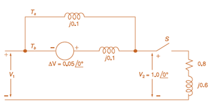
The per-unit equivalent circuit of two transformers T a and T b connected in parallel, with the same nominal voltage ratio and the same reactan of 0.1 per unit on the same base, is shown in Figure 3.43. Transformer T b has a voltage-magnitude step-up toward the load of 1.05 times that of T a (that is, the tap on the secondary winding of T b is set to 1.05). The load is represented by 0.8 + j 0.6 per unit at a voltage V 2 = 1 .0 / 0 ° per unit. Determine the complex power in per unit transmitted to the load through each transformer, comment on how the transformers share the real and reactive powers.
Solution Summary: The author explains the complex power in per unit supplied to the load through each transformer and the process of sharing real and reactive powers by transformer.
The per-unit equivalent circuit of two transformers
T
a
and
T
b
connected in parallel, with the same nominal voltage ratio and the same reactan of 0.1 per unit on the same base, is shown in Figure 3.43. Transformer
T
b
has a voltage-magnitude step-up toward the load of 1.05 times that of
T
a
(that is, the tap on the secondary winding of
T
b
is set to 1.05). The load is represented by
0.8
+
j
0.6
per unit at a voltage
V
2
=
1
.0
/
0
°
per unit. Determine the complex power in per unit transmitted to the load through each transformer, comment on how the transformers share the real and reactive powers.
Q5B. Find the type of the controller in the following figures and use real values to find the transfer
function of three of them[ Hint Pi,Pd and Lead,lag are found so put the controller with its
corresponding compensator].
R₁
R₂
Rz
HE
C2
RA
HE
R₁
R2
RA
と
Q1// Sketch the root locus for the unity feedback system. Where
G(s)=)=
K
S3+252 +25
and find the following
a. Sketch the asymptotes
b. The exact point and gain where the locus crosses the jo-axis
c. The breakaway point on the real axis
d. The range of K within which the system is stable
e. Angles of departure and arrival.
Determine X(w) for the given function shown in Figure (1) by applying the
differentiation property of the Fourier Transform.
Figure (1)
-1
x(t)
Need a deep-dive on the concept behind this application? Look no further. Learn more about this topic, electrical-engineering and related others by exploring similar questions and additional content below.


 Power System Analysis and Design (MindTap Course ...Electrical EngineeringISBN:9781305632134Author:J. Duncan Glover, Thomas Overbye, Mulukutla S. SarmaPublisher:Cengage Learning