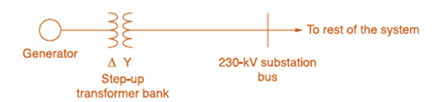
Consider the oneline diagram shown in Figure 3.40. The three-phase transformer bank is made up of three identical single-phase transformers, each specified by X 1 = 0.24 Ω (on the low-voltage side), negligible resistance and magnetizing current, and turns ratio η = N 2 / N 1 = 10 . The transformer bank is delivering 100 MW at 0.8 p.f. lagging to a substation bus whose voltage is 230 kV. (a) Determine the primary current magnitude, primary voltage (line-to-line) magnitude, and the three-phase complex power supplied by the generator. Choose the line-to-neutral voltage at the bus, V a ' η ' as the reference Account for the phase shift, and assume positive-sequence operation. (b) Find the phase shift between the primary and secondary voltages.
Consider the oneline diagram shown in Figure 3.40. The three-phase transformer bank is made up of three identical single-phase transformers, each specified by X 1 = 0.24 Ω (on the low-voltage side), negligible resistance and magnetizing current, and turns ratio η = N 2 / N 1 = 10 . The transformer bank is delivering 100 MW at 0.8 p.f. lagging to a substation bus whose voltage is 230 kV. (a) Determine the primary current magnitude, primary voltage (line-to-line) magnitude, and the three-phase complex power supplied by the generator. Choose the line-to-neutral voltage at the bus, V a ' η ' as the reference Account for the phase shift, and assume positive-sequence operation. (b) Find the phase shift between the primary and secondary voltages.
Solution Summary: The author calculates the power factor of a three-phase transformer bank, which is supplying 100MW at 0.8 pf lagging to the bus having voltage 230kV.
Consider the oneline diagram shown in Figure 3.40. The three-phase transformer bank is made up of three identical single-phase transformers, each specified by
X
1
=
0.24
Ω
(on the low-voltage side), negligible resistance and magnetizing current, and turns ratio
η
=
N
2
/
N
1
=
10
. The transformer bank is delivering 100 MW at 0.8 p.f. lagging to a substation bus whose voltage is 230 kV.
(a) Determine the primary current magnitude, primary voltage (line-to-line) magnitude, and the three-phase complex power supplied by the generator. Choose the line-to-neutral voltage at the bus,
V
a
'
η
'
as the reference Account for the phase shift, and assume positive-sequence operation.
(b) Find the phase shift between the primary and secondary voltages.
General Directions: Read the questions carefully and answer (3*10=30marks)
1. Design a summing amplifier by choosing appropriate values of resistors an so that
the output is 5 times the sum of the input voltages. (you are free to use any number
of inputs, the type of op-amp, any value of resistors)
2. Derive the equation for the closed loop gain of the inverting and non-inverting
Amplifier using appropriate circuit diagrams.
3. Determine the values read by the measuring devices using appropriate formulae
www
Voc
+8V
R₁
33 k
Rc
2.2 k
ww
WWW
Poc 200
R₁₂
RE
10 kn
1.0 kn
十
: + B
日
العنوان
I need a detailed drawing with explanation
ややハメPV+96252
4
Project Homework:
Create a simulation for a tank when the flowrate inside and outside the tank must
range between 0 and 10 lit/s:
1) The level should be controlled within a range between more than zero to 1000
lit.
2) An alarm must be launched when the level is out of range (less than 100 and
more than 900 lit).
3) When the capacity reaches to the maximum the motor turns OFF.
area=A
Qout
-20
solve in lab view
X9.01
*175*1
Project Homework:
Create a simulation for a tank when the flowrate inside and outside the tank must
range between 0 and 10 lit/s:
1) The level should be controlled within a range between more than zero to 1000
lit.
2) An alarm must be launched when the level is out of range (less than 100 and
more than 900 lit).
3) When the capacity reaches to the maximum the motor turns OFF.
Qin
h
C
Qout
area=A
solve in lab view
Need a deep-dive on the concept behind this application? Look no further. Learn more about this topic, electrical-engineering and related others by exploring similar questions and additional content below.


 Power System Analysis and Design (MindTap Course ...Electrical EngineeringISBN:9781305632134Author:J. Duncan Glover, Thomas Overbye, Mulukutla S. SarmaPublisher:Cengage Learning