
Power System Analysis & Design
6th Edition
ISBN: 9781305636187
Author: Glover, J. Duncan, Overbye, Thomas J. (thomas Jeffrey), Sarma, Mulukutla S.
Publisher: Cengage Learning,
expand_more
expand_more
format_list_bulleted
Concept explainers
Videos
Textbook Question
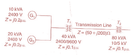
Chapter 3, Problem 3.28P
For the system shown in Figure 3.34. draw an impedance diagram in per unit by choosing 100 kVA to be the base kVA and 2400 V as the base voltage for the generators.
Expert Solution & Answer

Trending nowThis is a popular solution!

Students have asked these similar questions
Cable A
Cable A is a coaxial cable of constant cross section. The metal
regions are shaded in grey and are made of copper. The solid central
wire has radius a = 5mm, the outer tube inner radius b = 20mm and
thickness t = 5mm. The dielectric spacer is Teflon, of relative
permittivity &r = 2.1 and breakdown strength 350kV/cm. A potential
difference of 1kV is applied across the conductors, with centre
conductor positive and outer conductor earthed.
Before undertaking any COMSOL simulations we'll first perform some theoretical analysis
of Cable A based on the EN2076 lectures, to make sense of the simulations. Calculate the
radial electric field of cable A at radial positions r b. Also calculate the
maximum operating voltage of cable A, assuming a safety margin of ×2, and indicate where
on the cable's cross section dielectric breakdown is most likely to occur.
: For the gravity concrete dam shown in the figure, the following data are available:
The factor of safety against sliding (F.S sliding)=1.2
Unit weight of concrete (Yconc)=24 KN/m³
- Neglect( Wave pressure, silt pressure, ice force and earth quake force)
μ=0.65, (Ywater) = 9.81 KN/m³
Find factor of safety against overturning (F.S overturning)
6m3
80m
Sm
I need help checking if its correct
-E1 + VR1 + VR4 – E2 + VR3 = 0 -------> Loop 1 (a)
R1(I1) + R4(I1 – I2) + R3(I1) = E1 + E2 ------> Loop 1 (b)
R1(I1) + R4(I1) - R4(I2) + R3(I1) = E1 + E2 ------> Loop 1 (c)
(R1 + R3 + R4) (I1) - R4(I2) = E1 + E2 ------> Loop 1 (d)
Now that we have loop 1 equation will procced on finding the equation of I2 current loop. However, a reminder that because we are going in a clockwise direction, it goes against the direction of the current. As such we will get an equation for the matrix that will be:
E2 – VR4 – VR2 + E3 = 0 ------> Loop 2 (a)
-R4(I2 – I1) -R2(I2) = -E2 – E3 ------> Loop 2 (b)
-R4(I2) + R4(I1) - R2(I2) = -E2 – E3 -----> Loop 2 (c)
R4(I1) – (R4 + R2)(I2) = -E2 – E3 -----> Loop 2 (d)
These two equations will be implemented to the matrix formula I = inv(A) * b
R11 R12
(R1 + R3 + R4)
-R4
-R4
R4 + R2
Chapter 3 Solutions
Power System Analysis & Design
Ch. 3 - The Ohms law for the magnetic circuit states that...Ch. 3 - For an ideal transformer, the efficiency is (a) 0...Ch. 3 - For an ideal 2-winding transformer, the...Ch. 3 - An ideal transformer has no real or reactive power...Ch. 3 - For an ideal 2-winding transformer, an impedance...Ch. 3 - Consider Figure 3.4. For an ideal phase-shifting...Ch. 3 - Consider Figure 3.5. Match the following, those on...Ch. 3 - The units of admittance, conductance, and...Ch. 3 - Match the following: (i) Hysteresis loss (a) Can...Ch. 3 - For large power transformers rated more than 500...
Ch. 3 - For a short-circuit test on a 2-winding...Ch. 3 - The per-unit quantity is always dimensionless. (a)...Ch. 3 - Consider the adopted per-unit system for the...Ch. 3 - The ideal transformer windings are eliminated from...Ch. 3 - To convert a per-unit impedance from old to new...Ch. 3 - In developing per-unit circuits of systems such as...Ch. 3 - Prob. 3.17MCQCh. 3 - Prob. 3.18MCQCh. 3 - With the American Standard notation, in either a...Ch. 3 - Prob. 3.20MCQCh. 3 - In order to avoid difficulties with third-harmonic...Ch. 3 - Does an open connection permit balanced...Ch. 3 - Does an open- operation, the kVA rating compared...Ch. 3 - It is stated that (i) balanced three-phase...Ch. 3 - In developing per-unit equivalent circuits for...Ch. 3 - In per-unit equivalent circuits of practical...Ch. 3 - Prob. 3.27MCQCh. 3 - Prob. 3.28MCQCh. 3 - For developing per-unit equivalent circuits of...Ch. 3 - Prob. 3.30MCQCh. 3 - Prob. 3.31MCQCh. 3 - Prob. 3.32MCQCh. 3 - The direct electrical connection of the windings...Ch. 3 - Consider Figure 3.25 of the text for a transformer...Ch. 3 - (a) An ideal single-phase two-winding transformer...Ch. 3 - An ideal transformer with N1=1000andN2=250 is...Ch. 3 - Consider an ideal transformer with...Ch. 3 - A single-phase 100-kVA,2400/240-volt,60-Hz...Ch. 3 - Prob. 3.5PCh. 3 - Prob. 3.6PCh. 3 - Consider a source of voltage v(t)=102sin(2t)V,...Ch. 3 - Prob. 3.8PCh. 3 - Prob. 3.9PCh. 3 - A single-phase step-down transformer is rated...Ch. 3 - For the transformer in Problem 3.10. The...Ch. 3 - Prob. 3.12PCh. 3 - A single-phase 50-kVA,2400/240-volt,60-Hz...Ch. 3 - A single-phase 50-kVA,2400/240-volt,60-Hz...Ch. 3 - Rework Problem 3.14 if the transformer is...Ch. 3 - A single-phase, 50-kVA,2400/240-V,60-Hz...Ch. 3 - The transformer of Problem 3.16 is supplying a...Ch. 3 - Using the transformer ratings as base quantities,...Ch. 3 - Using the transformer ratings as base quantities....Ch. 3 - Using base values of 20 kVA and 115 volts in zone...Ch. 3 - Prob. 3.21PCh. 3 - A balanced Y-connected voltage source with...Ch. 3 - Figure 3.32 shows the oneline diagram of a...Ch. 3 - For Problem 3.18, the motor operates at full load,...Ch. 3 - Consider a single-phase electric system shown in...Ch. 3 - A bank of three single-phase transformers, each...Ch. 3 - A three-phase transformer is rated...Ch. 3 - For the system shown in Figure 3.34. draw an...Ch. 3 - Consider three ideal single-phase transformers...Ch. 3 - Reconsider Problem 3.29. If Va,VbandVc are a...Ch. 3 - Prob. 3.31PCh. 3 - Determine the positive- and negative-sequence...Ch. 3 - Consider the three single-phase two-winding...Ch. 3 - Three single-phase, two-winding transformers, each...Ch. 3 - Consider a bank of this single-phase two-winding...Ch. 3 - Three single-phase two-winding transformers, each...Ch. 3 - Three single-phase two-winding transformers, each...Ch. 3 - Consider a three-phase generator rated...Ch. 3 - The leakage reactance of a three-phase,...Ch. 3 - Prob. 3.40PCh. 3 - Consider the single-line diagram of the power...Ch. 3 - For the power system in Problem 3.41, the...Ch. 3 - Three single-phase transformers, each rated...Ch. 3 - A 130-MVA,13.2-kV three-phase generator, which has...Ch. 3 - Figure 3.39 shows a oneline diagram of a system in...Ch. 3 - The motors M1andM2 of Problem 3.45 have inputs of...Ch. 3 - Consider the oneline diagram shown in Figure 3.40....Ch. 3 - With the same transformer banks as in Problem...Ch. 3 - Consider the single-Line diagram of a power system...Ch. 3 - A single-phase three-winding transformer has the...Ch. 3 - The ratings of a three-phase three-winding...Ch. 3 - Prob. 3.52PCh. 3 - The ratings of a three-phase, three-winding...Ch. 3 - An infinite bus, which is a constant voltage...Ch. 3 - A single-phase l0-kVA,2300/230-volt,60-Hz...Ch. 3 - Three single-phase two-winding transformers, each...Ch. 3 - A two-winding single-phase transformer rated...Ch. 3 - A single-phase two-winding transformer rated...Ch. 3 - Prob. 3.59PCh. 3 - PowerWorid Simulator case Problem 3_60 duplicates...Ch. 3 - Rework Example 3.12 for a+10 tap, providing a 10...Ch. 3 - A 23/230-kV step-up transformer feeds a...Ch. 3 - The per-unit equivalent circuit of two...Ch. 3 - Reconsider Problem 3.64 with the change that now...Ch. 3 - What are the advantages of correctly specifying a...Ch. 3 - Why is it important to reduce the moisture within...Ch. 3 - What should be the focus of transformer preventive...
Knowledge Booster


Learn more about
Need a deep-dive on the concept behind this application? Look no further. Learn more about this topic, electrical-engineering and related others by exploring similar questions and additional content below.Similar questions
- 10.2 For each of the following groups of sources, determineif the three sources constitute a balanced source, and if it is,determine if it has a positive or negative phase sequence.(a) va(t) = 169.7cos(377t +15◦) Vvb(t) = 169.7cos(377t −105◦) Vvc(t) = 169.7sin(377t −135◦) V(b) va(t) = 311cos(wt −12◦) Vvb(t) = 311cos(wt +108◦) Vvc(t) = 311cos(wt +228◦) V(c) V1 = 140 −140◦ VV2 = 114 −20◦ VV3 = 124 100◦ Varrow_forwardApply single-phase equivalency to determine the linecurrents in the Y-D network shown in Fig. P10.13. The loadimpedances are Zab = Zbc = Zca = (25+ j5) Warrow_forward10.8 In the network of Fig. P10.8, Za = Zb = Zc = (25+ j5) W.Determine the line currents.arrow_forward
- Using D flip-flops, design a synchronous counter. The counter counts in the sequence 1,3,5,7, 1,7,5,3,1,3,5,7,.... when its enable input x is equal to 1; otherwise, the counter count 0. Present state Next state x=0 Next state x=1 Output SO 52 S1 1 S1 54 53 3 52 53 S2 56 51 0 $5 5 54 S4 53 0 55 58 57 7 56 56 55 0 57 S10 59 1 58 58 S7 0 59 S12 S11 7 $10 $10 59 0 $11 $14 $13 5 $12 S12 $11 0 513 $15 SO 3 S14 $14 S13 0 $15 515 SO 0 Explain how to get the table step by step with drawing the state diagram and finding the Karnaugh map.arrow_forwardFor the oscillator resonance circuit shown in Fig. (5), derive the oscillation frequency Feedback and open-loop gains. L₁ 5 mH (a) ell +10 V R₁ ww R3 S C2 HH 1 με 1000 pF 100 pF R₂ 1 με RA H (b) +9 V R4 CA 470 pF C₁ R3 HH 1 με R₁ ww L₁ 000 1.5 mH R₂ ww Hi 1 μF L2 m 10 mHarrow_forwardExpert handwritten solution onlyarrow_forward
- B. For the oscillator circuit shown in frequency, feedback and open-loop gains. +10 V name the circuit, derive and find the oscillation P.Av +9 V -000 4₁ 5 mH w R₁ C₂ HH 1 με w 100 pF R₂ T R CA www. 470 pF w ww www 1000 pF HH 1μF C₁ HH 1μF Ra ww HI 4₁ 000 1.5 mH H 4 AF 000 10 mHarrow_forwardI want to check if the current that I have from using the mesh analysis is correct? I1 = 0.214mA I2 = -0.429mAarrow_forwardI want to find the current by using mesh analysis pleasearrow_forward
- I want to find the current by using mesh analysis pleasearrow_forwardR₁ W +10 V R3 +9 V C₂ R₁ CA C₁ 470 pF HH 1000 pF HH 1 με C4 1 μF 1 uF C₁ R₂ R4 100 pF Find Open-loop Jain L₁ 5 mH (a) Av=S,B={" H R₁₂ ✓ ww (b) R₁ L₁ 000 1.5 mH R₂ H 1 uF 12 10 mHarrow_forwardA) Calculate the efficiency of the test transformer at the resistive loads (X-25%, 50%, 75%, 100%, 125% full load). B) From part (A) draw the plot (efficiency Vs power output) of the transformer. C) Discuss the plot of part (B).arrow_forward
arrow_back_ios
SEE MORE QUESTIONS
arrow_forward_ios
Recommended textbooks for you
 Power System Analysis and Design (MindTap Course ...Electrical EngineeringISBN:9781305632134Author:J. Duncan Glover, Thomas Overbye, Mulukutla S. SarmaPublisher:Cengage Learning
Power System Analysis and Design (MindTap Course ...
Electrical Engineering
ISBN:9781305632134
Author:J. Duncan Glover, Thomas Overbye, Mulukutla S. Sarma
Publisher:Cengage Learning
TRANSFORMERS - What They Are, How They Work, How Electricians Size Them; Author: Electrician U;https://www.youtube.com/watch?v=tXPy4OE7ApE;License: Standard Youtube License