Consider the single-line diagram of the power system shown in Figure 3.38. Equipment ratings are Generator 1: 1000 MVA, 18 kV, X" = 0 .2 per unit Generator 2: 1000 MVA, 18 kV, X" = 0 .2 p .u . Synchronous motor 3: 1500 MVA, 20 kV, X" = 0 .2 p .u . Three-phase Δ-Y transformers T 1 , T 2 , T 3 , T 4 , : 1000 MVA, 500 kV, Y/20 kV Δ , X = 0 .1 p .u . Three-phase Y − Y transformer T 5 : 1500 MVA, 500 kV, Y/20 kV Δ Y, X = 0 .1 p .u . Neglecting resistance, transformer phase shift, and magnetizing reactance, draw the equivalent reactance diagram. Use a base of 100 MA and 500 kV for the 50-ohm line. Determine the per-unit reactances.
Consider the single-line diagram of the power system shown in Figure 3.38. Equipment ratings are Generator 1: 1000 MVA, 18 kV, X" = 0 .2 per unit Generator 2: 1000 MVA, 18 kV, X" = 0 .2 p .u . Synchronous motor 3: 1500 MVA, 20 kV, X" = 0 .2 p .u . Three-phase Δ-Y transformers T 1 , T 2 , T 3 , T 4 , : 1000 MVA, 500 kV, Y/20 kV Δ , X = 0 .1 p .u . Three-phase Y − Y transformer T 5 : 1500 MVA, 500 kV, Y/20 kV Δ Y, X = 0 .1 p .u . Neglecting resistance, transformer phase shift, and magnetizing reactance, draw the equivalent reactance diagram. Use a base of 100 MA and 500 kV for the 50-ohm line. Determine the per-unit reactances.
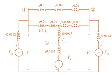
Solution Summary: The author explains how to draw a per unit equivalent reactance diagram.
Consider the single-line diagram of the power system shown in Figure 3.38. Equipment ratings are
Generator 1:
1000
MVA,
18
kV,
X"
=
0
.2
per
unit
Generator 2:
1000
MVA,
18
kV,
X"
=
0
.2
p
.u
.
Synchronous motor 3:
1500
MVA,
20
kV,
X"
=
0
.2
p
.u
.
Three-phase
Δ-Y
transformers
T
1
,
T
2
,
T
3
,
T
4
,
:
1000
MVA,
500
kV,
Y/20
kV
Δ
,
X
=
0
.1
p
.u
.
Three-phase
Y
−
Y
transformer
T
5
:
1500
MVA,
500
kV,
Y/20
kV
Δ
Y,
X
=
0
.1
p
.u
.
Neglecting resistance, transformer phase shift, and magnetizing reactance, draw the equivalent reactance diagram. Use a base of 100 MA and 500 kV for the 50-ohm line. Determine the per-unit reactances.
EXAMPLE 8.12 The E-MOSFET of Fig. 8.40 was analyzed in Example 7.10, with the
result that k = 0.24 × 10³ A/V², VGS = 6.4 V, and ID = 2.75 mA.
a. Determine gm-
b. Find rd.
c. Calculate Z; with and without rd. Compare results.
d. Find Zo with and without ra. Compare results.
e. Find A, with and without rd. Compare results.
카
1 uF
Z
RE
912 V
Rp
• 2 ΚΩ
10 ΜΩ
HE
1 μF
ID (on) = 6 mA
VGS (on) = 8 V
VGS (Th) = 3 V
80s = 20 μs
Za
o Vo
Need a deep-dive on the concept behind this application? Look no further. Learn more about this topic, electrical-engineering and related others by exploring similar questions and additional content below.
How does a Transformer work - Working Principle electrical engineering; Author: The Engineering Mindset;https://www.youtube.com/watch?v=UchitHGF4n8;License: Standard Youtube License


 Power System Analysis and Design (MindTap Course ...Electrical EngineeringISBN:9781305632134Author:J. Duncan Glover, Thomas Overbye, Mulukutla S. SarmaPublisher:Cengage Learning