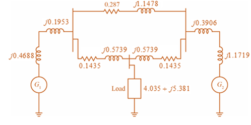
Consider the single-Line diagram of a power system shown in Figure 3.42 with equipment ratings given: Generator G 1 : 50 MVA, 13 .2 kV , x = 0.15 p .u . Generator G 2 : 20 MVA, 13 .8 kV , x = 0.15 p .u . Three-phase Δ-Y transformer T 1 : 80 MVA, 13 .2 Δ /165YkV , X = 0.1 p .u . Three-phase Y-Δ transformer T 2 : 40 MVA, 165 Y/13 .8 Δ kV , X = 0.1 p .u . Load: 40 MVA, 0.8 PF lagging, operating at 150 kV Choose a base of 100 MVA for the system and 132-kV base in the transmission-line circuit. Let the load be modeled as a parallel combination of resistance and inductance. Neglect transformer phase shifts. Draw a per-phase equivalent circuit of the system showing all impedances in per unit.
Consider the single-Line diagram of a power system shown in Figure 3.42 with equipment ratings given: Generator G 1 : 50 MVA, 13 .2 kV , x = 0.15 p .u . Generator G 2 : 20 MVA, 13 .8 kV , x = 0.15 p .u . Three-phase Δ-Y transformer T 1 : 80 MVA, 13 .2 Δ /165YkV , X = 0.1 p .u . Three-phase Y-Δ transformer T 2 : 40 MVA, 165 Y/13 .8 Δ kV , X = 0.1 p .u . Load: 40 MVA, 0.8 PF lagging, operating at 150 kV Choose a base of 100 MVA for the system and 132-kV base in the transmission-line circuit. Let the load be modeled as a parallel combination of resistance and inductance. Neglect transformer phase shifts. Draw a per-phase equivalent circuit of the system showing all impedances in per unit.
Solution Summary: The author calculates the base voltage for the generator 1 and transformer 1 circuit.
Consider the single-Line diagram of a power system shown in Figure 3.42 with equipment ratings given:
Generator
G
1
:
50
MVA,
13
.2
kV
,
x
=
0.15
p
.u
.
Generator
G
2
:
20
MVA,
13
.8
kV
,
x
=
0.15
p
.u
.
Three-phase
Δ-Y
transformer
T
1
:
80
MVA,
13
.2
Δ
/165YkV
,
X
=
0.1
p
.u
.
Three-phase
Y-Δ
transformer
T
2
:
40
MVA,
165
Y/13
.8
Δ
kV
,
X
=
0.1
p
.u
.
Load:
40
MVA,
0.8
PF
lagging,
operating
at
150
kV
Choose a base of 100 MVA for the system and 132-kV base in the transmission-line circuit. Let the load be modeled as a parallel combination of resistance and inductance. Neglect transformer phase shifts. Draw a per-phase equivalent circuit of the system showing all impedances in per unit.
I need handwritten solution to this, electrical engineering expert tutor s only,this is an assignment,I need 100% accuracy
5. Determine the CT convolutions for the signals below. Sketch the signal that flips and on same plot the
one that is not flipped. Do this for each overlap case. Clearly indicate all overlap cases and the integral
limits. Finally, using the left squiggly bracket notation, show the output for each case versus time.
(c) 4
x(t)
2
1
2(t) 4
x(t) 4
0123
et 20
x(t)
(4) 4
(a)
+(1)
24
T
0123
(b)
T
(f)
1
2-2
0123
(c)
(f)
0123
(d)
(1) A
t
1(8)
4,121
-101
3
(e)
Solve by pen and paper not using chatgpt or AI
Find the current io, and the voltage vo in the circuit in Figure 4. Answer: ἱο = 1.799 Α, νο = 17.99 V.
Need a deep-dive on the concept behind this application? Look no further. Learn more about this topic, electrical-engineering and related others by exploring similar questions and additional content below.
How does a Transformer work - Working Principle electrical engineering; Author: The Engineering Mindset;https://www.youtube.com/watch?v=UchitHGF4n8;License: Standard Youtube License


 Power System Analysis and Design (MindTap Course ...Electrical EngineeringISBN:9781305632134Author:J. Duncan Glover, Thomas Overbye, Mulukutla S. SarmaPublisher:Cengage Learning