
Concept explainers
Videos
3–1* to 3–4 Sketch a free-body diagram of each element in the figure. Compute the magnitude and direction of each force using an algebraic or
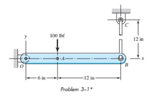
The free body diagram of each element of the given figure.
The magnitude and direction of each force.
Answer to Problem 1P
The free body diagram of element OB is shown in Figure (1).
The free body diagram of element BC is shown in Figure (2).
The free body diagram of pin joint C is shown in Figure (3).
The free body diagram of pin joint O is shown in Figure (4).
The magnitude of force at O is
The magnitude of force at B is
The magnitude of force at C is
Explanation of Solution
Figure (1) shows the free body diagram of the element OB.
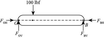
Figure (1)
Write the net moment at point O on the link OB.
Here, perpendicular distance between point O and
Write the net reaction force in the vertical direction on the link OB.
Here, force acting at point O is
Write the net reaction force in the horizontal direction on the link OB.
Here, force acting at point O is
Figure (2) shows the free body diagram of element BC.
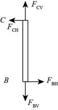
Figure (2)
Write the net reaction force in the horizontal direction on the link BC.
Here, force acting at point B is
Write the net reaction force in the vertical direction on the link OB.
Here, force acting at point C is
Figure (3) shows the free body diagram of pin joint C.
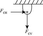
Figure (3)
Write the expression of net reaction force at pin joint C in horizontal direction.
Here, force acting at point C in the horizontal direction is
The force acting in the vertical direction at point C is balanced by the reaction force by link BC at point C.
Figure (4) shows the free body diagram of the pivot point O.
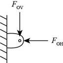
Figure (4)
Write the expression of net reaction force at pin joint O in horizontal direction.
Here, force acting at point O in the horizontal direction is
The force acting in the vertical direction at point O is balanced by the reaction force by link OB at point O.
Conclusion
Substitute
Thus, the vertical component of the force at point
Substitute
Thus, the vertical component of the force at point
Substitute
Thus, the vertical component of the force at point
Substitute
Thus, the horizontal component of the force at point
Substitute
Thus, the horizontal component of the force at point
Thus, the magnitude of force at O is
Thus, the magnitude of force at B is
Thus, the magnitude of force at C is
Want to see more full solutions like this?
Chapter 3 Solutions
Shigley's Mechanical Engineering Design (McGraw-Hill Series in Mechanical Engineering)
Additional Engineering Textbook Solutions
Vector Mechanics For Engineers
Modern Database Management
Thermodynamics: An Engineering Approach
Concepts Of Programming Languages
Automotive Technology: Principles, Diagnosis, And Service (6th Edition) (halderman Automotive Series)


- alpha 1 is not zero alpha 1 can equal alpha 2 use velocity triangle to solve for alpha 1 USE MATLAB ONLY provide typed code solve for velocity triangle and dont provide copied answer Turbomachienery . GIven: vx = 185 m/s, flow angle = 60 degrees, (leaving a stator in axial flow) R = 0.5, U = 150 m/s, b2 = -a3, a2 = -b3 Find: velocity triangle , a. magnitude of abs vel leaving rotor (m/s) b. flow absolute angles (a1, a2, a3) 3. flow rel angles (b2, b3) d. specific work done e. use code to draw vel. diagram Use this code for plot % plots Velocity Tri. in Ch4 function plotveltri(al1,al2,al3,b2,b3) S1L = [0 1]; V1x = [0 0]; V1s = [0 1*tand(al3)]; S2L = [2 3]; V2x = [0 0]; V2s = [0 1*tand(al2)]; W2s = [0 1*tand(b2)]; U2x = [3 3]; U2y = [1*tand(b2) 1*tand(al2)]; S3L = [4 5]; V3x = [0 0]; V3r = [0 1*tand(al3)]; W3r = [0 1*tand(b3)]; U3x = [5 5]; U3y = [1*tand(b3) 1*tand(al3)]; plot(S1L,V1x,'k',S1L,V1s,'r',... S2L,V2x,'k',S2L,V2s,'r',S2L,W2s,'b',U2x,U2y,'g',...…arrow_forward3. Find a basis of eigenvectors and diagonalize. 4 0 -19 7 a. b. 1-42 16 12-20 [21-61arrow_forward2. Find the eigenvalues. Find the corresponding eigenvectors. 6 2 -21 [0 -3 1 3 31 a. 2 5 0 b. 3 0 -6 C. 1 1 0 -2 0 7 L6 6 0 1 1 2. (Hint: λ = = 3)arrow_forward
- USE MATLAB ONLY provide typed code solve for velocity triangle and dont provide copied answer Turbomachienery . GIven: vx = 185 m/s, flow angle = 60 degrees, (leaving a stator in axial flow) R = 0.5, U = 150 m/s, b2 = -a3, a2 = -b3 Find: velocity triangle , a. magnitude of abs vel leaving rotor (m/s) b. flow absolute angles (a1, a2, a3) 3. flow rel angles (b2, b3) d. specific work done e. use code to draw vel. diagram Use this code for plot % plots Velocity Tri. in Ch4 function plotveltri(al1,al2,al3,b2,b3) S1L = [0 1]; V1x = [0 0]; V1s = [0 1*tand(al3)]; S2L = [2 3]; V2x = [0 0]; V2s = [0 1*tand(al2)]; W2s = [0 1*tand(b2)]; U2x = [3 3]; U2y = [1*tand(b2) 1*tand(al2)]; S3L = [4 5]; V3x = [0 0]; V3r = [0 1*tand(al3)]; W3r = [0 1*tand(b3)]; U3x = [5 5]; U3y = [1*tand(b3) 1*tand(al3)]; plot(S1L,V1x,'k',S1L,V1s,'r',... S2L,V2x,'k',S2L,V2s,'r',S2L,W2s,'b',U2x,U2y,'g',... S3L,V3x,'k',S3L,V3r,'r',S3L,W3r,'b',U3x,U3y,'g',...... 'LineWidth',2,'MarkerSize',10),...…arrow_forwardUSE MATLAB ONLY provide typed code solve for velocity triangle and dont provide copied answer Turbomachienery . GIven: vx = 185 m/s, flow angle = 60 degrees, R = 0.5, U = 150 m/s, b2 = -a3, a2 = -b3 Find: velocity triangle , a. magnitude of abs vel leaving rotor (m/s) b. flow absolute angles (a1, a2, a3) 3. flow rel angles (b2, b3) d. specific work done e. use code to draw vel. diagram Use this code for plot % plots Velocity Tri. in Ch4 function plotveltri(al1,al2,al3,b2,b3) S1L = [0 1]; V1x = [0 0]; V1s = [0 1*tand(al3)]; S2L = [2 3]; V2x = [0 0]; V2s = [0 1*tand(al2)]; W2s = [0 1*tand(b2)]; U2x = [3 3]; U2y = [1*tand(b2) 1*tand(al2)]; S3L = [4 5]; V3x = [0 0]; V3r = [0 1*tand(al3)]; W3r = [0 1*tand(b3)]; U3x = [5 5]; U3y = [1*tand(b3) 1*tand(al3)]; plot(S1L,V1x,'k',S1L,V1s,'r',... S2L,V2x,'k',S2L,V2s,'r',S2L,W2s,'b',U2x,U2y,'g',... S3L,V3x,'k',S3L,V3r,'r',S3L,W3r,'b',U3x,U3y,'g',...... 'LineWidth',2,'MarkerSize',10),... axis([-1 6 -4 4]), ...…arrow_forwardThe answer should equal to 1157. Please sent me the solution. Thank you!arrow_forward
- BONUS: If the volume of the 8cm x 6.5cm x 6cm Block of Aluminum was 312cm3 before machining, find how much material was removed when the fixture below was machined. +2 2.00 cm 6.00 cm 2.50 cm 6.50 cm 1.00 cm 2.50 cm 11.00 cm 8.00 cm 30 CP 9411 FL.4) (m² 1157 Area of triangle = 1/2*B*H Area of circle = лR² Circumference of a circle = 2πR 6.00 cm 6.50 cm 1.50 cm Radius 1.50 cm 1.00 cmarrow_forwardConsider a 5m by 5m wet concret patio with an average water film thickness of .2mm. Now wind at 50 km/h is blowing over the surface. If the air is at 1 atm, 15oC and 35 percent relative humidity, determine how long it will take for the patio to completely dry.arrow_forward70. Compute the number of cubic centimeters of iron required for the cast-iron plate shown. The plate is 3.50 centimeters thick. Round the answer to the nearest cubic centimeter. 50.0 cm 40.0 cm Radius 150° 115.0 cm- 81.0 cmarrow_forward
- Law of Sines Solve the following problems using the Law of Sin 7. Find side x. All dimensions are in inches. -°-67°-37° 81° x Sin A 8.820 X 67°00' 32°00' a sin A b C sin B sin Carrow_forward35. a. Determine B. b. Determine side b. c. Determine side c. 5.330 in.- ZB 73°30'arrow_forwardConsider a 12 cm internal diameter, 14 m long circular duct whose interior surface is wet. The duct is to be dried by forcing dry air at 1 atm and 15 degrees C throught it at an average velocity of 3m/s. The duct passes through a chilled roo, and it remains at an average temp of 15 degrees C at all time. Determine the mass transfer coeeficient in the duct.arrow_forward
 Mechanics of Materials (MindTap Course List)Mechanical EngineeringISBN:9781337093347Author:Barry J. Goodno, James M. GerePublisher:Cengage Learning