The student engineer of a campus radio station wishes to verify the effectiveness of the lightning rod on the antenna mast (Fig. P27.49). The unknown resistance R x is between points C and E . Point E is a true ground, but it is inaccessible for direct measurement because this stratum is several meters below the Earth’s surface. Two identical rods are driven into the ground at A and B , introducing an unknown resistance R y . The procedure is as follows. Measure resistance R 1 between points A and B , then connect A and B with a heavy conducting wire and measure resistance R 2 between points A and C . (a) Derive an equation for R x in terms of the observable resistances, R 1 , and R 2 . (b) A satisfactory ground resistance would R x < 2.00 Ω. Is the grounding of the station adequate if measurements give R 1 = 13.0 Ω and R 2 = 6.00 Ω? Explain. Figure P27.49
The student engineer of a campus radio station wishes to verify the effectiveness of the lightning rod on the antenna mast (Fig. P27.49). The unknown resistance R x is between points C and E . Point E is a true ground, but it is inaccessible for direct measurement because this stratum is several meters below the Earth’s surface. Two identical rods are driven into the ground at A and B , introducing an unknown resistance R y . The procedure is as follows. Measure resistance R 1 between points A and B , then connect A and B with a heavy conducting wire and measure resistance R 2 between points A and C . (a) Derive an equation for R x in terms of the observable resistances, R 1 , and R 2 . (b) A satisfactory ground resistance would R x < 2.00 Ω. Is the grounding of the station adequate if measurements give R 1 = 13.0 Ω and R 2 = 6.00 Ω? Explain. Figure P27.49
Solution Summary: The author explains the equation for R_x in terms of the observable resistances.
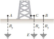
The student engineer of a campus radio station wishes to verify the effectiveness of the lightning rod on the antenna mast (Fig. P27.49). The unknown resistance Rx is between points C and E. Point E is a true ground, but it is inaccessible for direct measurement because this stratum is several meters below the Earth’s surface. Two identical rods are driven into the ground at A and B, introducing an unknown resistance Ry. The procedure is as follows. Measure resistance R1 between points A and B, then connect A and B with a heavy conducting wire and measure resistance R2 between points A and C. (a) Derive an equation for Rx in terms of the observable resistances, R1, and R2. (b) A satisfactory ground resistance would Rx < 2.00 Ω. Is the grounding of the station adequate if measurements give R1 = 13.0 Ω and R2 = 6.00 Ω? Explain.
4.) The diagram shows the electric field lines of a positively charged conducting sphere of
radius R and charge Q.
A
B
Points A and B are located on the same field line.
A proton is placed at A and released from rest. The magnitude of the work done by the electric field in
moving the proton from A to B is 1.7×10⁻¹⁶ J. Point A is at a distance of 5.0×10⁻²m from the centre of
the sphere. Point B is at a distance of 1.0×10⁻¹ m from the centre of the sphere.
(a) Explain why the electric potential decreases from A to B. [2]
(b) Draw, on the axes, the variation of electric potential V with distance r from the centre of the
sphere.
R
[2]
(c(i)) Calculate the electric potential difference between points A and B. [1]
(c(ii)) Determine the charge Q of the sphere. [2]
(d) The concept of potential is also used in the context of gravitational fields. Suggest why scientists
developed a common terminology to describe different types of fields. [1]
3.) The graph shows how current I varies with potential difference V across a component X.
904
80-
70-
60-
50-
I/MA
40-
30-
20-
10-
0+
0
0.5
1.0 1.5 2.0 2.5 3.0 3.5 4.0 4.5 5.0
VIV
Component X and a cell of negligible internal resistance are placed in a circuit.
A variable resistor R is connected in series with component X. The ammeter reads 20mA.
4.0V
4.0V
Component X and the cell are now placed in a potential divider circuit.
(a) Outline why component X is considered non-ohmic. [1]
(b(i)) Determine the resistance of the variable resistor. [3]
(b(ii)) Calculate the power dissipated in the circuit. [1]
(c(i)) State the range of current that the ammeter can measure as the slider S of the potential divider
is moved from Q to P. [1]
(c(ii)) Describe, by reference to your answer for (c)(i), the advantage of the potential divider
arrangement over the arrangement in (b).
Chapter 28 Solutions
Physics for Scientists and Engineers, Technology Update (No access codes included)
Need a deep-dive on the concept behind this application? Look no further. Learn more about this topic, physics and related others by exploring similar questions and additional content below.
DC Series circuits explained - The basics working principle; Author: The Engineering Mindset;https://www.youtube.com/watch?v=VV6tZ3Aqfuc;License: Standard YouTube License, CC-BY


 Physics for Scientists and Engineers: Foundations...PhysicsISBN:9781133939146Author:Katz, Debora M.Publisher:Cengage Learning
 Principles of Physics: A Calculus-Based TextPhysicsISBN:9781133104261Author:Raymond A. Serway, John W. JewettPublisher:Cengage Learning
 College PhysicsPhysicsISBN:9781938168000Author:Paul Peter Urone, Roger HinrichsPublisher:OpenStax College
 Physics for Scientists and EngineersPhysicsISBN:9781337553278Author:Raymond A. Serway, John W. JewettPublisher:Cengage Learning
 Physics for Scientists and Engineers with Modern ...PhysicsISBN:9781337553292Author:Raymond A. Serway, John W. JewettPublisher:Cengage Learning