
Videos
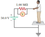
For the purpose of measuring the electric resistance of shoes through the body of the wearer standing on a metal ground plate, the American National Standards Institute (ANSI) specifies the circuit shown in Figure P27.14. The potential difference ΔV across the 1.00-MΩ resistor is measured with an ideal voltmeter. (a) Show that the resistance of the footwear is
(b) In a medical test, a current through the human body should not exceed 150 μA. Can the current delivered by the ANSI-specified circuit exceed 150 μA? To decide, consider a person standing barefoot on the ground plate.
Figure P27.14

Trending nowThis is a popular solution!

Chapter 28 Solutions
Physics for Scientists and Engineers, Technology Update (No access codes included)


- TICE D Conservation of Momentum 1. A 63.0 kg astronaut is on a spacewalk when the tether line to the shuttle breaks. The astronaut is able to throw a spare 10.0 kg oxygen tank in a direction away from the shuttle with a speed of 12.0 m/s, propelling the astronaut back to the shuttle. Assuming that the astronaut starts from rest with respect to the shuttle, find the astronaut's final speed with respect to the shuttle after the tank is thrown. 2. An 85.0 kg fisherman jumps from a dock into a 135.0 kg rowboat at rest on the west side of the dock. If the velocity of the fisherman is 4.30 m/s to the west as he leaves the dock, what is the final velocity of the fisher- man and the boat? 3. Each croquet ball in a set has a mass of 0.50 kg. The green ball, traveling at 12.0 m/s, strikes the blue ball, which is at rest. Assuming that the balls slide on a frictionless surface and all collisions are head-on, find the final speed of the blue ball in each of the following situations: a. The green…arrow_forwardThe 5.15 A current through a 1.50 H inductor is dissipated by a 2.15 Q resistor in a circuit like that in the figure below with the switch in position 2. 0.632/ C A L (a) 0.368/ 0+ 0 = L/R 2T 3r 4 (b) (a) What is the initial energy (in J) in the inductor? 0 t = L/R 2t (c) Эт 4t 19.89 ] (b) How long will it take (in s) the current to decline to 5.00% of its initial value? 2.09 S (c) Calculate the average power (in W) dissipated, and compare it with the initial power dissipated by the resistor. 28.5 1.96 x W X (ratio of initial power to average power)arrow_forwardImagine a planet where gravity mysteriously acts tangent to the equator and in the eastward directioninstead of radially inward. Would this force do work on an object moving on the earth? What is the sign ofthe work, and does it depend on the path taken? Explain by using the work integral and provide a sketch ofthe force and displacement vectors. Provide quantitative examples.arrow_forward
- If a force does zero net work on an object over a closed loop, does that guarantee the force is conservative? Explain with an example or counterexamplearrow_forwardA futuristic amusement ride spins riders in a horizontal circle of radius 5 m at a constant speed. Thefloor drops away, leaving riders pinned to the wall by friction (coefficient µ = 0.4). What minimum speedensures they don’t slip, given g = 10 m/s²? Draw diagram (or a few) showing all forces, thevelocity of the rider, and their accelerationarrow_forwardYour RL circuit has a characteristic time constant of 19.5 ns, and a resistance of 4.60 MQ. (a) What is the inductance (in H) of the circuit? 0.00897 × H (b) What resistance (in MQ) should you use (instead of the 4.60 MQ resistor) to obtain a 1.00 ns time constant, perhaps needed for quick response in an oscilloscope? 8.97 * ΜΩarrow_forward
- Your RL circuit has a characteristic time constant of 19.5 ns, and a resistance of 4.60 MQ. (a) What is the inductance (in H) of the circuit? H (b) What resistance (in MQ) should you use (instead of the 4.60 MQ resistor) to obtain a 1.00 ns time constant, perhaps needed for quick response in an oscilloscope? ΜΩarrow_forwardAt a distance of 0.212 cm from the center of a charged conducting sphere with radius 0.100cm, the electric field is 485 N/C . What is the electric field 0.598 cm from the center of the sphere? At a distance of 0.196 cmcm from the axis of a very long charged conducting cylinder with radius 0.100cm, the electric field is 485 N/C . What is the electric field 0.620 cm from the axis of the cylinder? At a distance of 0.202 cm from a large uniform sheet of charge, the electric field is 485 N/C . What is the electric field 1.21 cm from the sheet?arrow_forwardA hollow, conducting sphere with an outer radius of 0.260 m and an inner radius of 0.200 m has a uniform surface charge density of +6.67 × 10⁻⁶ C/m2. A charge of -0.800 μC is now introduced into the cavity inside the sphere. What is the new charge density on the outside of the sphere? Calculate the strength of the electric field just outside the sphere. What is the electric flux through a spherical surface just inside the inner surface of the sphere?arrow_forward
- A point charge of -3.00 μC is located in the center of a spherical cavity of radius 6.60 cm inside an insulating spherical charged solid. The charge density in the solid is 7.35 × 10⁻⁴ C/m3. Calculate the magnitude of the electric field inside the solid at a distance of 9.10 cm from the center of the cavity. Find the direction of this electric field.arrow_forwardAn infinitely long conducting cylindrical rod with a positive charge λ per unit length is surrounded by a conducting cylindrical shell (which is also infinitely long) with a charge per unit length of −2λ and radius r1, as shown in the figure. What is E(r), the radial component of the electric field between the rod and cylindrical shell as a function of the distance r from the axis of the cylindrical rod? Express your answer in terms of λ, r, and ϵ0, the permittivity of free space. What is σinner, the surface charge density (charge per unit area) on the inner surface of the conducting shell? What is σouterσouter, the surface charge density on the outside of the conducting shell? (Recall from the problem statement that the conducting shell has a total charge per unit length given by −2λ.) What is the radial component of the electric field, E(r), outside the shell?arrow_forwardA very long conducting tube (hollow cylinder) has inner radius aa and outer radius b. It carries charge per unit length +α, where αα is a positive constant with units of C/m. A line of charge lies along the axis of the tube. The line of charge has charge per unit length +α. Calculate the electric field in terms of α and the distance r from the axis of the tube for r<a. Calculate the electric field in terms of α and the distance rr from the axis of the tube for a<r<b. Calculate the electric field in terms of αα and the distance r from the axis of the tube for r>b. What is the charge per unit length on the inner surface of the tube? What is the charge per unit length on the outer surface of the tube?arrow_forward
 Principles of Physics: A Calculus-Based TextPhysicsISBN:9781133104261Author:Raymond A. Serway, John W. JewettPublisher:Cengage Learning
 Physics for Scientists and EngineersPhysicsISBN:9781337553278Author:Raymond A. Serway, John W. JewettPublisher:Cengage Learning
 Physics for Scientists and Engineers with Modern ...PhysicsISBN:9781337553292Author:Raymond A. Serway, John W. JewettPublisher:Cengage Learning
 College PhysicsPhysicsISBN:9781305952300Author:Raymond A. Serway, Chris VuillePublisher:Cengage Learning
 College PhysicsPhysicsISBN:9781938168000Author:Paul Peter Urone, Roger HinrichsPublisher:OpenStax College