
Physics for Scientists and Engineers, Technology Update (No access codes included)
9th Edition
ISBN: 9781305116399
Author: Raymond A. Serway, John W. Jewett
Publisher: Cengage Learning
expand_more
expand_more
format_list_bulleted
Videos
Textbook Question
Chapter 28, Problem 28.42P
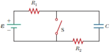
In the circuit of Figure P27.25, the switch S has been open for a long time. It is then suddenly closed. Determine the time constant (a) before the switch is closed and (b) after the switch is closed. (c) Let the switch be closed at t = 0. Determine the current in the switch as a function of time.
Figure P27.25 Problems 25 and 26.
Expert Solution & Answer

Trending nowThis is a popular solution!

Students have asked these similar questions
No chatgpt pls will upvote
No chatgpt pls will upvote instant
Kirchoff's Laws. A circuit contains 3 known resistors, 2 known batteries, and 3 unknown currents as shown.
Assume the current flows through the circuit as shown (this is our initial guess, the actual currents may be
reverse). Use the sign convention that a potential drop is negative and a potential gain is positive.
E₂ = 8V
R₁₁ = 50
R₂ = 80
b
с
w
11
www
12
13
E₁ = 6V
R3 = 20
a) Apply Kirchoff's Loop Rule around loop abefa in the clockwise direction starting at point a. (2 pt).
b) Apply Kirchoff's Loop Rule around loop bcdeb in the clockwise direction starting at point b. (2 pt).
c) Apply Kirchoff's Junction Rule at junction b (1 pt).
d) Solve the above 3 equations for the unknown currents I1, 12, and 13 and specify the direction of the current
around each loop. (5 pts)
I1 =
A
12 =
A
13 =
A
Direction of current around loop abef
Direction of current around loop bcde
(CW or CCW)
(CW or CCW)
Chapter 28 Solutions
Physics for Scientists and Engineers, Technology Update (No access codes included)
Ch. 28 - To maximize the percentage of the power from the...Ch. 28 - With the switch in the circuit of Figure 27.4a...Ch. 28 - With the switch in the circuit of Figure 27.6a...Ch. 28 - Prob. 28.4QQCh. 28 - Consider the circuit in Figure 27.17 and assume...Ch. 28 - Is a circuit breaker wired (a) in series with the...Ch. 28 - A battery has some internal resistance. (i) Clan...Ch. 28 - The terminals of a battery are connected across...Ch. 28 - When operating on a 120-V circuit, an electric...Ch. 28 - If the terminals of a battery with zero internal...
Ch. 28 - Prob. 28.6OQCh. 28 - What is the time constant of the circuit shown in...Ch. 28 - When resistors with different resistances are...Ch. 28 - When resistors with different resistances are...Ch. 28 - The terminals of a battery are connected across...Ch. 28 - Are the two headlights of a car wired (a) in...Ch. 28 - In the circuit shown in Figure OQ28.12, each...Ch. 28 - Prob. 28.13OQCh. 28 - A circuit consists of three identical lamps...Ch. 28 - A series circuit consists of three identical lamps...Ch. 28 - Suppose a parachutist lands on a high-voltage wire...Ch. 28 - A student claims that the second of two lightbulbs...Ch. 28 - Why is ii possible for a bird to sit on a...Ch. 28 - Given three lightbulbs and a battery, sketch as...Ch. 28 - Prob. 28.5CQCh. 28 - Referring to Figure CQ28.6, describe what happens...Ch. 28 - Prob. 28.7CQCh. 28 - (a) What advantage does 120-V operation offer over...Ch. 28 - Prob. 28.9CQCh. 28 - Prob. 28.10CQCh. 28 - A battery has an emf of 15.0 V. The terminal...Ch. 28 - Two 1.50-V batterieswith their positive terminals...Ch. 28 - An automobile battery has an emf of 12.6 V and 171...Ch. 28 - As in Example 27.2, consider a power supply with...Ch. 28 - Three 100- resistors are connected as shown in...Ch. 28 - Prob. 28.6PCh. 28 - What is the equivalent resistance of the...Ch. 28 - Consider the two circuits shown in Figure P27.5 in...Ch. 28 - Consider the circuit shown in Figure P28.9. Find...Ch. 28 - (a) You need a 45- resistor, but the stockroom has...Ch. 28 - A battery with = 6.00 V and no internal...Ch. 28 - A battery with emf and no internal resistance...Ch. 28 - (a) Kind the equivalent resistance between points...Ch. 28 - (a) When the switch S in the circuit of Figure...Ch. 28 - Prob. 28.15PCh. 28 - Four resistors are connected to a battery as shown...Ch. 28 - Consider die combination of resistors shown in...Ch. 28 - For the purpose of measuring the electric...Ch. 28 - Calculate the power delivered to each resistor in...Ch. 28 - Why is the following situation impossible? A...Ch. 28 - Consider the circuit shown in Figure P28.21 on...Ch. 28 - In Figure P28.22, show how to add just enough...Ch. 28 - The circuit shown in Figure P27.17 is connected...Ch. 28 - For the circuit shown in Figure P28.24, calculate...Ch. 28 - What are the expected readings of (a) the ideal...Ch. 28 - The following equations describe an electric...Ch. 28 - Taking R = 1.00 k and = 250 V in Figure P27.19,...Ch. 28 - You have a faculty position at a community college...Ch. 28 - The ammeter shown in Figure P28.29 reads 2.00 A....Ch. 28 - In the circuit of Figure P28.30, determine (a) the...Ch. 28 - Using Kirchhoffs rules, (a) find (he current in...Ch. 28 - In the circuit of Figure P27.20, the current I1 =...Ch. 28 - In Figure P28.33, find (a) the current in each...Ch. 28 - For the circuit shown in Figure P27.22, we wish to...Ch. 28 - Find the potential difference across each resistor...Ch. 28 - (a) Can the circuit shown in Figure P27.21 be...Ch. 28 - An uncharged capacitor and a resistor are...Ch. 28 - Consider a series RC circuit as in Figure P28.38...Ch. 28 - A 2.00-nF capacitor with an initial charge of 5.10...Ch. 28 - A 10.0-F capacitor is charged by a 10.0-V battery...Ch. 28 - In the circuit of Figure P27.25, the switch S has...Ch. 28 - In the circuit of Figure P27.25, the switch S has...Ch. 28 - The circuit in Figure P28.43 has been connected...Ch. 28 - Show that the integral 0e2t/RCdtin Example 27.11...Ch. 28 - A charged capacitor is connected to a resistor and...Ch. 28 - Prob. 28.46PCh. 28 - Prob. 28.47PCh. 28 - Turn on your desk lamp. Pick up the cord, with...Ch. 28 - Assume you have a battery of emf and three...Ch. 28 - Find the equivalent resistance between points a...Ch. 28 - Four 1.50-V AA batteries in series are used to...Ch. 28 - Four resistors are connected in parallel across a...Ch. 28 - The circuit in Figure P27.35 has been connected...Ch. 28 - The circuit in Figure P27.34a consists of three...Ch. 28 - For the circuit shown in Figure P28.55. the ideal...Ch. 28 - The resistance between terminals a and b in Figure...Ch. 28 - (a) Calculate the potential difference between...Ch. 28 - Why is the following situation impossible? A...Ch. 28 - A rechargeable battery has an emf of 13.2 V and an...Ch. 28 - Find (a) the equivalent resistance of the circuit...Ch. 28 - When two unknown resistors are connected in series...Ch. 28 - When two unknown resistors are connected in series...Ch. 28 - The- pair of capacitors in Figure P28.63 are fully...Ch. 28 - A power supply has an open-circuit voltage of 40.0...Ch. 28 - The circuit in Figure P27.41 contains two...Ch. 28 - Two resistors R1 and R2 are in parallel with each...Ch. 28 - Prob. 28.67APCh. 28 - A battery is used to charge a capacitor through a...Ch. 28 - A young man owns a canister vacuum cleaner marked...Ch. 28 - (a) Determine the equilibrium charge on the...Ch. 28 - Switch S shown in Figure P28.71 has been closed...Ch. 28 - Three identical 60.0-W, 120-V lightbulbs are...Ch. 28 - A regular tetrahedron is a pyramid with a...Ch. 28 - An ideal voltmeter connected across a certain...Ch. 28 - In Figure P27.47, suppose the switch has been...Ch. 28 - Figure P27.48 shows a circuit model for the...Ch. 28 - The student engineer of a campus radio station...Ch. 28 - The circuit shown in Figure P28.78 is set up in...Ch. 28 - An electric teakettle has a multiposition switch...Ch. 28 - A voltage V is applied to a series configuration...Ch. 28 - In places such as hospital operating rooms or...Ch. 28 - The switch in Figure P27.51a closes when Vc23Vand...Ch. 28 - The resistor R in Figure P28.83 receives 20.0 W of...
Knowledge Booster


Learn more about
Need a deep-dive on the concept behind this application? Look no further. Learn more about this topic, physics and related others by exploring similar questions and additional content below.Similar questions
- No chatgpt pls will upvotearrow_forward4.) The diagram shows the electric field lines of a positively charged conducting sphere of radius R and charge Q. A B Points A and B are located on the same field line. A proton is placed at A and released from rest. The magnitude of the work done by the electric field in moving the proton from A to B is 1.7×10⁻¹⁶ J. Point A is at a distance of 5.0×10⁻²m from the centre of the sphere. Point B is at a distance of 1.0×10⁻¹ m from the centre of the sphere. (a) Explain why the electric potential decreases from A to B. [2] (b) Draw, on the axes, the variation of electric potential V with distance r from the centre of the sphere. R [2] (c(i)) Calculate the electric potential difference between points A and B. [1] (c(ii)) Determine the charge Q of the sphere. [2] (d) The concept of potential is also used in the context of gravitational fields. Suggest why scientists developed a common terminology to describe different types of fields. [1]arrow_forward3.) The graph shows how current I varies with potential difference V across a component X. 904 80- 70- 60- 50- I/MA 40- 30- 20- 10- 0+ 0 0.5 1.0 1.5 2.0 2.5 3.0 3.5 4.0 4.5 5.0 VIV Component X and a cell of negligible internal resistance are placed in a circuit. A variable resistor R is connected in series with component X. The ammeter reads 20mA. 4.0V 4.0V Component X and the cell are now placed in a potential divider circuit. (a) Outline why component X is considered non-ohmic. [1] (b(i)) Determine the resistance of the variable resistor. [3] (b(ii)) Calculate the power dissipated in the circuit. [1] (c(i)) State the range of current that the ammeter can measure as the slider S of the potential divider is moved from Q to P. [1] (c(ii)) Describe, by reference to your answer for (c)(i), the advantage of the potential divider arrangement over the arrangement in (b).arrow_forward
- 1.) Two long parallel current-carrying wires P and Q are separated by 0.10 m. The current in wire P is 5.0 A. The magnetic force on a length of 0.50 m of wire P due to the current in wire Q is 2.0 × 10-s N. (a) State and explain the magnitude of the force on a length of 0.50 m of wire Q due to the current in P. [2] (b) Calculate the current in wire Q. [2] (c) Another current-carrying wire R is placed parallel to wires P and Q and halfway between them as shown. wire P wire R wire Q 0.05 m 0.05 m The net magnetic force on wire Q is now zero. (c.i) State the direction of the current in R, relative to the current in P.[1] (c.ii) Deduce the current in R. [2]arrow_forward2.) A 50.0 resistor is connected to a cell of emf 3.00 V. The voltmeter and the ammeter in the circuit are ideal. V A 50.00 (a) The current in the ammeter is 59.0 mA. Calculate the internal resistance of the cell. The circuit is changed by connecting another resistor R in parallel to the 50.0 resistor. V A 50.00 R (b) Explain the effect of this change on R is made of a resistive wire of uniform cross-sectional area 3.1 × 10⁻⁸ m², resistivity 4.9 × 10-70m and length L. The resistance of R is given by the equation R = KL where k is a constant. (b.i) the reading of the ammeter. [2] (b.ii) the reading of the voltmeter. [2] (c) Calculate k. State an appropriate unit for your answer. [3] [2]arrow_forwardNo chatgpt pls will upvotearrow_forward
- No chatgpt pls will upvotearrow_forwardA rod 12.0 cm long is uniformly charged and has a total charge of -20.0 μc. Determine the magnitude and direction of the electric field along the axis of the rod at a point 32.0 cm from its center. 361000 ☑ magnitude What is the general expression for the electric field along the axis of a uniform rod? N/C direction toward the rodarrow_forwardA certain brand of freezer is advertised to use 730 kW h of energy per year. Part A Assuming the freezer operates for 5 hours each day, how much power does it require while operating? Express your answer in watts. ΜΕ ΑΣΦ ? P Submit Request Answer Part B W If the freezer keeps its interior at a temperature of -6.0° C in a 20.0° C room, what is its theoretical maximum performance coefficient? Enter your answer numerically. K = ΜΕ ΑΣΦ Submit Request Answer Part C What is the theoretical maximum amount of ice this freezer could make in an hour, starting with water at 20.0°C? Express your answer in kilograms. m = Ο ΑΣΦ kgarrow_forward
- Describe the development of rational choice theory in sociology. Please includearrow_forwardA-E pleasearrow_forwardA 11.8 L gas tank containing 3.90 moles of ideal He gas at 26.0°C is placed inside a completely evacuated insulated bell jar of volume 39.0 L .A small hole in the tank allows the He to leak out into the jar until the gas reaches a final equilibrium state with no more leakage. Part A What is the change in entropy of this system due to the leaking of the gas? ■ ΜΕ ΑΣΦ AS = ? J/K Submit Request Answer Part B Is the process reversible or irreversible?arrow_forward
arrow_back_ios
SEE MORE QUESTIONS
arrow_forward_ios
Recommended textbooks for you
 Physics for Scientists and EngineersPhysicsISBN:9781337553278Author:Raymond A. Serway, John W. JewettPublisher:Cengage Learning
 Physics for Scientists and Engineers with Modern ...PhysicsISBN:9781337553292Author:Raymond A. Serway, John W. JewettPublisher:Cengage Learning
 Principles of Physics: A Calculus-Based TextPhysicsISBN:9781133104261Author:Raymond A. Serway, John W. JewettPublisher:Cengage Learning
 Physics for Scientists and Engineers: Foundations...PhysicsISBN:9781133939146Author:Katz, Debora M.Publisher:Cengage Learning
 Physics for Scientists and Engineers, Technology ...PhysicsISBN:9781305116399Author:Raymond A. Serway, John W. JewettPublisher:Cengage Learning
Physics for Scientists and Engineers
Physics
ISBN:9781337553278
Author:Raymond A. Serway, John W. Jewett
Publisher:Cengage Learning
Physics for Scientists and Engineers with Modern ...
Physics
ISBN:9781337553292
Author:Raymond A. Serway, John W. Jewett
Publisher:Cengage Learning
Principles of Physics: A Calculus-Based Text
Physics
ISBN:9781133104261
Author:Raymond A. Serway, John W. Jewett
Publisher:Cengage Learning
Physics for Scientists and Engineers: Foundations...
Physics
ISBN:9781133939146
Author:Katz, Debora M.
Publisher:Cengage Learning
Physics for Scientists and Engineers, Technology ...
Physics
ISBN:9781305116399
Author:Raymond A. Serway, John W. Jewett
Publisher:Cengage Learning
What is Electromagnetic Induction? | Faraday's Laws and Lenz Law | iKen | iKen Edu | iKen App; Author: Iken Edu;https://www.youtube.com/watch?v=3HyORmBip-w;License: Standard YouTube License, CC-BY