
Concept explainers
Videos
Reduce each of the networks shown in Figure P2.1 to a single equivalent resistance by combining resistances in series and parallel.
* Denotes that answers are contained in the Student Solutions flies. See Appendix E for more information about accessing the Student Solutions
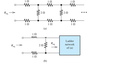
FIgure P2.1
(a)
The equivalent resistance by combining resistance in series.
Answer to Problem 2.1P
The value of equivalent resistance is
Explanation of Solution
Calculation:
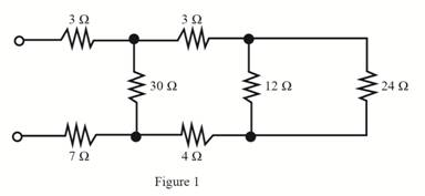
The required diagram is shown in Figure 1.
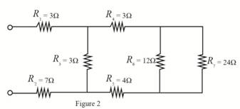
Mark the resistance
The required diagram is shown in Figure 2.
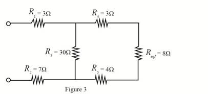
The value of resistance
Substitute
The required diagram is shown in Figure 3.
The value of resistance
Substitute
The required diagram is shown in Figure 4.
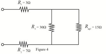
The value of resistance
Substitute
The required diagram is shown in Figure 5.
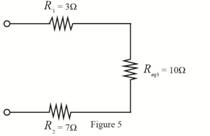
The value of resistance
Substitute
The required diagram is shown in Figure 6.
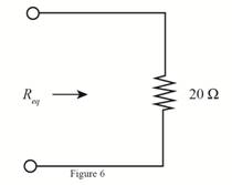
Conclusion:
Therefore, the value of equivalent resistance is
(b)
The equivalent resistance by combining resistance in series.
Answer to Problem 2.1P
The value of equivalent resistance is
Explanation of Solution
Calculation:
The required diagram is shown in Figure 7.
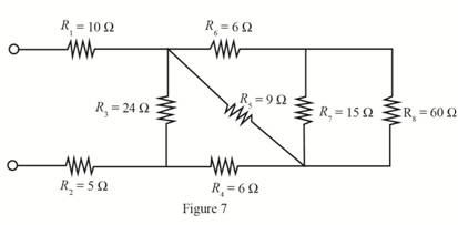
The value of resistance
Substitute
The required diagram is shown in Figure 8.
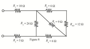
The value of resistance
Substitute
The equivalent resistance is shown in Figure 9.
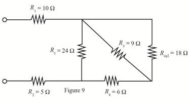
The value of resistance
Substitute
The required diagram is shown in Figure 10.
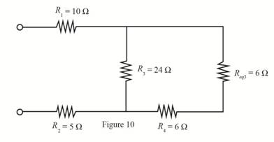
The value of resistance
Substitute
The equivalent resistance is shown in Figure 11.
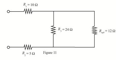
The value of resistance
Substitute
The required diagram is shown in Figure 12.
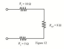
The value of resistance
Substitute
The required diagram is shown in Figure 13.
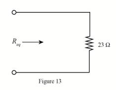
Conclusion:
Therefore, the value of equivalent resistance is
Want to see more full solutions like this?
Chapter 2 Solutions
Electrical Engineering: Principles & Applications (7th Edition)


- Solve this experiment with an accurate solution, please. Thank you.arrow_forwardA lossless uncharged transmission line of characteristic impedance Zo = 600 and length T = 1us is connected to a 180 load. If this transmission line is connected at t = 0 to a 90 V dc source with an internal resistance of 900, from a bounce diagram of this system sketch (a) the voltage at z=0, z=L, and z = L/2 for up to 7.25μs and (b) calculate the load voltage after an infinite amount of time.arrow_forwardA lossless uncharged transmission line of length L = 0.45 cm has a characteristic impedance of 60 ohms. It is driven by an ideal voltage generator producing a pulse of amplitude 10V and width 2 nS. If the transmission line is connected to a load of 200 ohms, sketch the voltage at the load as a function of time for the interval 0 < t < 20 nS. You may assume that the propagation velocity of the transmission is c/2.arrow_forward
- The VSWR (Voltage Standing Wave Ratio) is measured to be 2 on a transmission line. Find two values of the reflection coefficient with one corresponding to Z > Zo and the other to Zarrow_forwardA dc voltage of unknown value Vand internal resistance Reis connected through a switch to a lossless transmission line of Zo = 1000. If the first 5 μS of the voltages at z = 0 and z = L are observed to be as shown below, calculate Vo, RG, the load resistanceR,, and the transit time T. 100 + [V]:-0. V 90 [V]:-V 100 75 I, Տ 1,μs 2 4 6 0 2 4 6arrow_forwardA lossless open circuited transmission line behaves as an equivalent capacitance of Ceq = Tan (BL) Show for BL << 1 that Ceq = C'L where L is the length of the transmission line and wZo C' is the lumped parameter capacitance per unit length of the transmission line. Hint: For x small, Tan(x) = x.arrow_forward= A generator with VG 300V and R = 50 is connected to a load R = 750 through a 50 lossless transmission line of length L = 0.15 m. (a) Compute Zin, the input impedance of the line at the generator end. (b) Compute and V. (c) Compute the time-average power Pin delivered to the line. (d) Compute VL, IL, and the time-average power delivered to the load, PL (e) How does Pin compare to PL? Explain.arrow_forwardFor the regulated power supply circuit, assume regular diodes with 0.7V forward drop. Use a 15V (peak), 60Hz sine wave at the transformer secondary and assume a maximum ripple level of 1V. (a) Compute the unknown components needed to design 10V DC supply.Hint: find R first, and then C. What is the ripple level for C=22µF?Sketch the rectified, filtered, and regulated outputsarrow_forwardA) Find the solution of B) Find the convolution of Sewt (t-π)dt 8 e-atu(t)e-blu(t)arrow_forwardConsider the signal: f(t)= 0, ㅠ 1 Use the Fourier transform formula to find F(w). otherwisearrow_forwardA half-wave controlled rectifier is supplied by a 230 Vrms voltage source and has load resistance of 2502. Calculate the delay angle a that produces a load-absorbed power of 200W.arrow_forwardQ6 The FET shown in Fig. 1.43 has gm = 3.4 mS and rd =100 K. Find the approximate lower cutoff frequency. Ans: 735.1 Hz. 25V 1.5ΜΩ 20 ΚΩ 0.02µF HH 2ΚΩ 0.02µF HH 330kQ 820 ΩΣ 1.0µF www 40ΚΩarrow_forwardarrow_back_iosSEE MORE QUESTIONSarrow_forward_ios
 Delmar's Standard Textbook Of ElectricityElectrical EngineeringISBN:9781337900348Author:Stephen L. HermanPublisher:Cengage Learning