
Electrical Engineering: Principles & Applications (7th Edition)
7th Edition
ISBN: 9780134484143
Author: Allan R. Hambley
Publisher: PEARSON
expand_more
expand_more
format_list_bulleted
Concept explainers
Videos
Textbook Question
Chapter 2, Problem 2.33P
Refer to the circuit shown in Figure P2.33. With the switch open, we have v2=8 V. On the other hand, with the switch closed, we have v2=6 V. Determine the values of R2 and RL.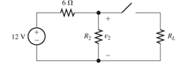
Figure P2.33
Expert Solution & Answer
Want to see the full answer?
Check out a sample textbook solution
Students have asked these similar questions
2-1) Lathi & Ding prob. 2.5-2 For the signals y(t) and x(t) shown below, find the component of the form
y(t) contained in x(t). In other words, find the optimum value of c in the approximation x(t) = cy(t) so that
the error signal energy is minimum. Also compute the error signal energy.
y(t)
x(t)
0
1
0
1
1. Is1 = 2ls2 = 4 × 10-16 A, B₁ = ẞ2 = 100, and R₁ = 5 kQ. Find the VB such that lx = 1 mA.
(30 points)
R1
ww
Q2
+
VB
Figure 1
2-2) Lathi & Ding prob. 2.6-1
2.6-1 Find the correlation coefficient p between of signal x(t) and each of the four pulses g1(1), 82(1),
83(1), and g4(f) shown in Fig. P2.6-1. To provide maximum margin against the noise along the
transmission path, which pair of pulses would you select for a binary communication?
Figure P.2.6-1
x(f)
(a)
8(1)
(b)
82(1)
(c)
1
1
sin 2πt
sin 4πt
-sin 2
0
0.707
83(1)
0
1
(d)
0
M
P
0.707
84(1)
(e)
0
0.5
-0.707
Chapter 2 Solutions
Electrical Engineering: Principles & Applications (7th Edition)
Ch. 2 - Reduce each of the networks shown in Figure P2.1...Ch. 2 - A 4- resistance is in series with the parallel...Ch. 2 - Find the equivalent resistance looking into...Ch. 2 - Suppose that we need a resistance of 1.5 k and...Ch. 2 - Find the equivalent resistance between terminals a...Ch. 2 - Find the equivalent resistance between terminals a...Ch. 2 - What resistance in parallel with 120 results in...Ch. 2 - Determine the resistance between terminals a and b...Ch. 2 - Two resistances having values of R and 2R are in...Ch. 2 - A network connected between terminals a and b...
Ch. 2 - Two resistances R1 and R2 are connected in...Ch. 2 - Find the equivalent resistance for the infinite...Ch. 2 - If we connect n 1000- resistances in parallel,...Ch. 2 - The heating element of an electric cook top has...Ch. 2 - We are designing an electric space heater to...Ch. 2 - Sometimes, we can use symmetry considerations to...Ch. 2 - The equivalent resistance between terminals a and...Ch. 2 - Three conductances G1 G2, and G3 are in series....Ch. 2 - Most sources of electrical power behave as...Ch. 2 - The resistance for the network shown in Figure...Ch. 2 - Often, we encounter delta-connected loads such as...Ch. 2 - What are the steps in solving a circuit by network...Ch. 2 - Find the values of i1 and i2 in Figure P2.23....Ch. 2 - Find the voltages v1 and v2 for the circuit shown...Ch. 2 - Find the values of v and i in Figure P2.25. Figure...Ch. 2 - Consider the circuit shown in Figure P2.24....Ch. 2 - Find the voltage v and the currents i1 and 12 for...Ch. 2 - Find the values of vs, v1, and i2 in Figure P2.28....Ch. 2 - Find the values of i1 and i2 in Figure P2.29....Ch. 2 - Consider the cirrcuit shown in Figure P2.30 Find...Ch. 2 - Solve for the values of i1, i2, and the powers for...Ch. 2 - The 12-V source in Figure P2.32 is delivering 36...Ch. 2 - Refer to the circuit shown in Figure P2.33. With...Ch. 2 - Find the values of i1 and i2 in Figure P2.34. Find...Ch. 2 - Find the values of i1 and i2 in Figure P2.35...Ch. 2 - Use the voltage-division principle to calculate...Ch. 2 - Use the current-division principle to calculate i1...Ch. 2 - Use the voltage-division principle to calculate...Ch. 2 - Use the current-division principle to calculate...Ch. 2 - Suppose we need to design a voltage-divider...Ch. 2 - A source supplies 120 V to the series combination...Ch. 2 - We have a 60- resistance, a 20- resistance, and...Ch. 2 - A worker is standing on a wet concrete floor,...Ch. 2 - Suppose we have a load that absorbs power and...Ch. 2 - We have a load resistance of 50 that we wish to...Ch. 2 - We have a load resistance of 1 k that we wish to...Ch. 2 - The circuit of Figure P2.47 is similar to networks...Ch. 2 - Write equations and solve for the node voltages...Ch. 2 - Solve for the node voltages shown in Figure P2.49....Ch. 2 - Solve for the node voltages shown in Figure P2.50....Ch. 2 - Given R1=4 , R2=5 , R2=8 , R4=10 , R5=2 , and...Ch. 2 - Determine the value of i1 in Figure P2.52 using...Ch. 2 - Given R1=15 , R5=5 , R3=20 , R4=10 , R5=8 , R6=4 ,...Ch. 2 - In solving a network, what rule must you observe...Ch. 2 - Use the symbolic features of MATLAB to find an...Ch. 2 - Solve for the values of the node voltages shown in...Ch. 2 - Solve for the node voltages shown in Figure P2.57....Ch. 2 - Solve for the power delivered to the 8- ...Ch. 2 - Solve for the node voltages shown in Figure P2.59....Ch. 2 - Find the equivalent resistance looking into...Ch. 2 - Find the equivalent resistance looking into...Ch. 2 - Figure P2.62 shows an unusual voltage-divider...Ch. 2 - Solve for the node voltages in the circuit of...Ch. 2 - We have a cube with 1- resistances along each...Ch. 2 - Solve for the power delivered to the 15- resistor...Ch. 2 - Determine the value of v2 and the power delivered...Ch. 2 - Use mesh-current analysis to find the value of i1...Ch. 2 - Solve for the power delivered by the voltage...Ch. 2 - Use mesh-current analysis to find the value of v...Ch. 2 - Use mesh-current analysis to find the value of i3...Ch. 2 - Use mesh-current analysis to find the values of i1...Ch. 2 - Find the power delivered by the source and the...Ch. 2 - Use mesh-current analysis to find the values of i1...Ch. 2 - Use mesh-current analysis to find the values of i1...Ch. 2 - The circuit shown in Figure P2.75 is the dc...Ch. 2 - Use MATLAB and mesh-current analysis to determine...Ch. 2 - Connect a 1-V voltage source across terminals a...Ch. 2 - Connect a 1-V voltage source across the terminals...Ch. 2 - Use MATLAB to solve for the mesh currents in...Ch. 2 - Find the Thévenin and Norton equivalent circuits...Ch. 2 - We can model a certain battery as a voltage source...Ch. 2 - Find the Thévenin and Norton equivalent circuits...Ch. 2 - Find the Thévenin and Norton equivalent circuits...Ch. 2 - Find the Thévenin arid Norton equivalent circuits...Ch. 2 - An automotive battery has an open-circuit voltage...Ch. 2 - A certain two-terminal circuit has an open-circuit...Ch. 2 - If we measure the voltage at the terminals of a...Ch. 2 - Find the Thévenin and Norton equivalent circuits...Ch. 2 - Find the maximum power that can be delivered to a...Ch. 2 - Find the maximum power that can be delivered to a...Ch. 2 - Figure P2.91 shows a resistive load RL connected...Ch. 2 - Starling from the Norton equivalent circuit with a...Ch. 2 - A battery can be modeled by a voltage source Vt in...Ch. 2 - Use superposition to find the current i in Figure...Ch. 2 - Solve for is in Figure P2.49 by using...Ch. 2 - Solve the circuit shown in Figure P2.48 by using...Ch. 2 - Solve for i1 in Figure P2.34 by using...Ch. 2 - Another method of solving the circuit of Figure...Ch. 2 - Use the method of Problem P2.98 for the circuit of...Ch. 2 - Solve for the actual value of i6 for the circuit...Ch. 2 - Device A shown in Figure P2.101 has v=3i2 for i 0...Ch. 2 - The Wheatstone bridge shown in Figure 2.66 is...Ch. 2 - The Wheatstone bridge shown in Figure 2.66has...Ch. 2 - In theory, any values can be used for R1 and R3 in...Ch. 2 - Derive expressions for the Thévenin voltage and...Ch. 2 - Derive Equation 2.93 for the bridge circuit of...Ch. 2 - Prob. 2.107PCh. 2 - Explain what would happen if, in wiring the bridge...Ch. 2 - Match each entry in Table T2.1(a) with the best...Ch. 2 - Consider the circuit of Figure T2.2 with vs=96V ,...Ch. 2 - Write MATLAB code to solve for the node voltages...Ch. 2 - Write a set of equations that can be used to solve...Ch. 2 - Determine the Thévenin and Norton equivalent...Ch. 2 - According to the superposition principle, what...Ch. 2 - Determine the equivalent resistance between...Ch. 2 - Transform the 2-A current source and 6- ...
Knowledge Booster


Learn more about
Need a deep-dive on the concept behind this application? Look no further. Learn more about this topic, electrical-engineering and related others by exploring similar questions and additional content below.Similar questions
- 2. Determine the operation point and the small-signal model of Q₁ for each of the circuits shown in Fig. 2. Assume Is = 8 × 10-16 A, B = 100 and VA = ∞. a) 20 points b) 20 points 0.8 V RC 50 Ω + Vcc = 2.5 V 4A" Figure 2-a Rc1kQ + Vcc = 2.5 V Figure 2-barrow_forwardPlease explain in detail how to solve this question. Show detailed steps in terms of calculation and theory. thank youarrow_forwardPls show neat and whole solutionarrow_forward
- Pls show neat and whole solutionarrow_forwardPlease explain in detail how to solve this question. Include steps with calculations and theory. thank youarrow_forwardFinding crystallographic direction Z pt. 2 head pt. 1: ៩ Example 2: pt. 1 x₁ = a, y₁ = b/2, z₁ = 0 pt. 2 x2=-a, y₂ = b, Z₂ = c -a-a b-b/2 c-0 a b c tail => -2, 1/2, 1 Multiplying by 2 to eliminate the fraction -4,1,2 => [412] where the overbar represents a negative index families of directionsarrow_forward
- Crystallographic planes Crystallographic planes are denoted by Miller indices. 5b Algorithm for Miller indices 1. Read off intercepts of plane with axes in terms of a, b, c 2. Take reciprocals of intercepts 3. Reduce to smallest integer values 4. Enclose in parentheses, no commas. 353 1/3 1/5 1/3 535 (535) In the cubic system, a plane and a direction with the same indices are orthogonal. E.g. [100] direction is perpendicular to (100) plane. Correspondingly, [123] direction is perpendicular to (123) plane. [2,3,3] Plane intercepts axes at 3a, 2b, 2c 2 11 1 Reciprocal numbers are: 3'2'2 b. Indices of the plane (Miller): (2,3,3) 2 a Indices of the direction: [2,3,3] X (200) (100) (110) (111) (100) Indices of crystallographic plane can be found from cross product of indices of any two non-parallel directions in this plane.arrow_forwardCrystallographic positions Crystallographic position is denoted by three numbers, which are coefficients of the position vector, e.g. ½½½ for the red atom. Here the 'new' atom is at a/2 + b/2 + c/2 Silicon crystal has so-called "diamond type lattice". Each Si atom has 4 nearest neighbors. Diamond lattice starts with a FCC lattice and then adds four additional INTERNAL atoms at locations r = a/4+b/4+c/4 away from each of the atoms. In other words, diamond lattice is formed by two FCC lattices sifted by the vector r.arrow_forwardfind the answers for this prelabarrow_forward
- Q2: (30 Marks) Design a DC/DC converter that produce output waveforms that shown in figures below from a fixed DC source of 20 volts. Vo (Volt) 14.1 IL (Amp) 13.9 2.25 1.75 † (msec) Output voltage 0.18 0.2 t (msec) L 0.214 0.22 Output currentarrow_forward6. Build the circuit shown in Figure 2 below in PSpice. Note that the power supply V1 is a VSIN power supply in the SOURCE library. Vcc is a VDC supply found in the SOURCE library. Model this circuit using the Time Domain (Transient) Analysis Type with a Run To Time of 2 ms. A. Paste your output graph showing the voltage at the base terminal, collector terminal and at the load. B. What is the voltage gain of the circuit? (Compare the voltage amplitude at the base terminal input (across Rb2) to that at the collector terminal. C. What happens to the output voltage at the collector terminal if the value of Rb1 is reduced by a factor of 10 (to 14.7 kn)? Simulate this situation and explain the result. D. What happens to the output voltage at the collector terminal if the value of Rb1 is increased by a factor of 3 (to 441 k)? Simulate this situation and explain the result. Rb1 RC 147k 1k C2 C1 Q1 Vcc 1u VOFF = 0 Q2N3904 10Vdc VAMPL = 0.1V1 1u FREQ = 2k R_load Rb2 Re AC = 0 250 40k 20 Figure…arrow_forwardThe input reactance of 1/2 dipole with radius of 1/30 is given as shown in figure below, Assuming the wire of dipole is conductor 5.6*107 S/m, determine at f=1 GHz the a-Loss resistance, b- Radiation efficiency c-Reflection efficiency when the antenna is connected to T.L shown in the figure. Rr Ro= 50 2 1/4 RL -j100 [In(l/a) - 1.5] tan(ẞl)arrow_forward
arrow_back_ios
SEE MORE QUESTIONS
arrow_forward_ios
Recommended textbooks for you
 Introductory Circuit Analysis (13th Edition)Electrical EngineeringISBN:9780133923605Author:Robert L. BoylestadPublisher:PEARSON
 Delmar's Standard Textbook Of ElectricityElectrical EngineeringISBN:9781337900348Author:Stephen L. HermanPublisher:Cengage Learning
 Programmable Logic ControllersElectrical EngineeringISBN:9780073373843Author:Frank D. PetruzellaPublisher:McGraw-Hill Education
 Fundamentals of Electric CircuitsElectrical EngineeringISBN:9780078028229Author:Charles K Alexander, Matthew SadikuPublisher:McGraw-Hill Education
 Electric Circuits. (11th Edition)Electrical EngineeringISBN:9780134746968Author:James W. Nilsson, Susan RiedelPublisher:PEARSON
 Engineering ElectromagneticsElectrical EngineeringISBN:9780078028151Author:Hayt, William H. (william Hart), Jr, BUCK, John A.Publisher:Mcgraw-hill Education,
Introductory Circuit Analysis (13th Edition)
Electrical Engineering
ISBN:9780133923605
Author:Robert L. Boylestad
Publisher:PEARSON
Delmar's Standard Textbook Of Electricity
Electrical Engineering
ISBN:9781337900348
Author:Stephen L. Herman
Publisher:Cengage Learning
Programmable Logic Controllers
Electrical Engineering
ISBN:9780073373843
Author:Frank D. Petruzella
Publisher:McGraw-Hill Education
Fundamentals of Electric Circuits
Electrical Engineering
ISBN:9780078028229
Author:Charles K Alexander, Matthew Sadiku
Publisher:McGraw-Hill Education
Electric Circuits. (11th Edition)
Electrical Engineering
ISBN:9780134746968
Author:James W. Nilsson, Susan Riedel
Publisher:PEARSON
Engineering Electromagnetics
Electrical Engineering
ISBN:9780078028151
Author:Hayt, William H. (william Hart), Jr, BUCK, John A.
Publisher:Mcgraw-hill Education,
Current Divider Rule; Author: Neso Academy;https://www.youtube.com/watch?v=hRU1mKWUehY;License: Standard YouTube License, CC-BY