
Electrical Engineering: Principles & Applications (7th Edition)
7th Edition
ISBN: 9780134484143
Author: Allan R. Hambley
Publisher: PEARSON
expand_more
expand_more
format_list_bulleted
Concept explainers
Videos
Textbook Question
Chapter 2, Problem 2.80P
Find the Thévenin and Norton equivalent circuits for the two-terminal circuit shown in Figure P2.80. 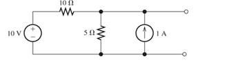
Figure P2.80
Expert Solution & Answer

Learn your wayIncludes step-by-step video

schedule08:14
Students have asked these similar questions
2 Find Inverse Fourier transform of
F(jw)
=
2w
-16+w2, and plot the f(t).
Need Handwritten Solution. Do not use chatgpt or AI
Solve by pen & paper without using chatgpt or AI
Mesh analysis
Chapter 2 Solutions
Electrical Engineering: Principles & Applications (7th Edition)
Ch. 2 - Reduce each of the networks shown in Figure P2.1...Ch. 2 - A 4- resistance is in series with the parallel...Ch. 2 - Find the equivalent resistance looking into...Ch. 2 - Suppose that we need a resistance of 1.5 k and...Ch. 2 - Find the equivalent resistance between terminals a...Ch. 2 - Find the equivalent resistance between terminals a...Ch. 2 - What resistance in parallel with 120 results in...Ch. 2 - Determine the resistance between terminals a and b...Ch. 2 - Two resistances having values of R and 2R are in...Ch. 2 - A network connected between terminals a and b...
Ch. 2 - Two resistances R1 and R2 are connected in...Ch. 2 - Find the equivalent resistance for the infinite...Ch. 2 - If we connect n 1000- resistances in parallel,...Ch. 2 - The heating element of an electric cook top has...Ch. 2 - We are designing an electric space heater to...Ch. 2 - Sometimes, we can use symmetry considerations to...Ch. 2 - The equivalent resistance between terminals a and...Ch. 2 - Three conductances G1 G2, and G3 are in series....Ch. 2 - Most sources of electrical power behave as...Ch. 2 - The resistance for the network shown in Figure...Ch. 2 - Often, we encounter delta-connected loads such as...Ch. 2 - What are the steps in solving a circuit by network...Ch. 2 - Find the values of i1 and i2 in Figure P2.23....Ch. 2 - Find the voltages v1 and v2 for the circuit shown...Ch. 2 - Find the values of v and i in Figure P2.25. Figure...Ch. 2 - Consider the circuit shown in Figure P2.24....Ch. 2 - Find the voltage v and the currents i1 and 12 for...Ch. 2 - Find the values of vs, v1, and i2 in Figure P2.28....Ch. 2 - Find the values of i1 and i2 in Figure P2.29....Ch. 2 - Consider the cirrcuit shown in Figure P2.30 Find...Ch. 2 - Solve for the values of i1, i2, and the powers for...Ch. 2 - The 12-V source in Figure P2.32 is delivering 36...Ch. 2 - Refer to the circuit shown in Figure P2.33. With...Ch. 2 - Find the values of i1 and i2 in Figure P2.34. Find...Ch. 2 - Find the values of i1 and i2 in Figure P2.35...Ch. 2 - Use the voltage-division principle to calculate...Ch. 2 - Use the current-division principle to calculate i1...Ch. 2 - Use the voltage-division principle to calculate...Ch. 2 - Use the current-division principle to calculate...Ch. 2 - Suppose we need to design a voltage-divider...Ch. 2 - A source supplies 120 V to the series combination...Ch. 2 - We have a 60- resistance, a 20- resistance, and...Ch. 2 - A worker is standing on a wet concrete floor,...Ch. 2 - Suppose we have a load that absorbs power and...Ch. 2 - We have a load resistance of 50 that we wish to...Ch. 2 - We have a load resistance of 1 k that we wish to...Ch. 2 - The circuit of Figure P2.47 is similar to networks...Ch. 2 - Write equations and solve for the node voltages...Ch. 2 - Solve for the node voltages shown in Figure P2.49....Ch. 2 - Solve for the node voltages shown in Figure P2.50....Ch. 2 - Given R1=4 , R2=5 , R2=8 , R4=10 , R5=2 , and...Ch. 2 - Determine the value of i1 in Figure P2.52 using...Ch. 2 - Given R1=15 , R5=5 , R3=20 , R4=10 , R5=8 , R6=4 ,...Ch. 2 - In solving a network, what rule must you observe...Ch. 2 - Use the symbolic features of MATLAB to find an...Ch. 2 - Solve for the values of the node voltages shown in...Ch. 2 - Solve for the node voltages shown in Figure P2.57....Ch. 2 - Solve for the power delivered to the 8- ...Ch. 2 - Solve for the node voltages shown in Figure P2.59....Ch. 2 - Find the equivalent resistance looking into...Ch. 2 - Find the equivalent resistance looking into...Ch. 2 - Figure P2.62 shows an unusual voltage-divider...Ch. 2 - Solve for the node voltages in the circuit of...Ch. 2 - We have a cube with 1- resistances along each...Ch. 2 - Solve for the power delivered to the 15- resistor...Ch. 2 - Determine the value of v2 and the power delivered...Ch. 2 - Use mesh-current analysis to find the value of i1...Ch. 2 - Solve for the power delivered by the voltage...Ch. 2 - Use mesh-current analysis to find the value of v...Ch. 2 - Use mesh-current analysis to find the value of i3...Ch. 2 - Use mesh-current analysis to find the values of i1...Ch. 2 - Find the power delivered by the source and the...Ch. 2 - Use mesh-current analysis to find the values of i1...Ch. 2 - Use mesh-current analysis to find the values of i1...Ch. 2 - The circuit shown in Figure P2.75 is the dc...Ch. 2 - Use MATLAB and mesh-current analysis to determine...Ch. 2 - Connect a 1-V voltage source across terminals a...Ch. 2 - Connect a 1-V voltage source across the terminals...Ch. 2 - Use MATLAB to solve for the mesh currents in...Ch. 2 - Find the Thévenin and Norton equivalent circuits...Ch. 2 - We can model a certain battery as a voltage source...Ch. 2 - Find the Thévenin and Norton equivalent circuits...Ch. 2 - Find the Thévenin and Norton equivalent circuits...Ch. 2 - Find the Thévenin arid Norton equivalent circuits...Ch. 2 - An automotive battery has an open-circuit voltage...Ch. 2 - A certain two-terminal circuit has an open-circuit...Ch. 2 - If we measure the voltage at the terminals of a...Ch. 2 - Find the Thévenin and Norton equivalent circuits...Ch. 2 - Find the maximum power that can be delivered to a...Ch. 2 - Find the maximum power that can be delivered to a...Ch. 2 - Figure P2.91 shows a resistive load RL connected...Ch. 2 - Starling from the Norton equivalent circuit with a...Ch. 2 - A battery can be modeled by a voltage source Vt in...Ch. 2 - Use superposition to find the current i in Figure...Ch. 2 - Solve for is in Figure P2.49 by using...Ch. 2 - Solve the circuit shown in Figure P2.48 by using...Ch. 2 - Solve for i1 in Figure P2.34 by using...Ch. 2 - Another method of solving the circuit of Figure...Ch. 2 - Use the method of Problem P2.98 for the circuit of...Ch. 2 - Solve for the actual value of i6 for the circuit...Ch. 2 - Device A shown in Figure P2.101 has v=3i2 for i 0...Ch. 2 - The Wheatstone bridge shown in Figure 2.66 is...Ch. 2 - The Wheatstone bridge shown in Figure 2.66has...Ch. 2 - In theory, any values can be used for R1 and R3 in...Ch. 2 - Derive expressions for the Thévenin voltage and...Ch. 2 - Derive Equation 2.93 for the bridge circuit of...Ch. 2 - Prob. 2.107PCh. 2 - Explain what would happen if, in wiring the bridge...Ch. 2 - Match each entry in Table T2.1(a) with the best...Ch. 2 - Consider the circuit of Figure T2.2 with vs=96V ,...Ch. 2 - Write MATLAB code to solve for the node voltages...Ch. 2 - Write a set of equations that can be used to solve...Ch. 2 - Determine the Thévenin and Norton equivalent...Ch. 2 - According to the superposition principle, what...Ch. 2 - Determine the equivalent resistance between...Ch. 2 - Transform the 2-A current source and 6- ...
Additional Engineering Textbook Solutions
Find more solutions based on key concepts
What is the general problem with static scoping?
Concepts Of Programming Languages
#inc1ude iostream; using namespace std; int main() { char name, go; cout Enter your name: ; getline name; cou...
Starting Out with C++ from Control Structures to Objects (9th Edition)
What is an object? What is a control?
Starting Out With Visual Basic (8th Edition)
2-1 List the five types of measurements that form the
basis of traditional ptane surveying-
Elementary Surveying: An Introduction To Geomatics (15th Edition)
Summarize the steps performed by the CPU when an interrupt occurs.
Computer Science: An Overview (13th Edition) (What's New in Computer Science)
Method fahrenheit returns the Fahrenheit equivalent of a Celsius temperature, using the calculation fahrenheit ...
Java How to Program, Early Objects (11th Edition) (Deitel: How to Program)
Knowledge Booster


Learn more about
Need a deep-dive on the concept behind this application? Look no further. Learn more about this topic, electrical-engineering and related others by exploring similar questions and additional content below.Similar questions
- 49. For the circuit below, what is the best connection of the capacitor to filte voltage? ბი DO A O BO wwwww wwwww M m H E LOADarrow_forward5.25. Determine the corner frequency resulting from Cin in Fig. 5.47(d). For simplicity, assume C₁ is a short circuit. TVDD C₁ M2 RF Vin H w - Vout Cin M₁arrow_forwardIn the below circuit, find out the value of equivalent Thevenin's voltage and Thevenin's resistance at the terminal. 2000 0.25 A 400 2 800 2 0.1 Aarrow_forward
- Q1: For the circuit shown in Figure-1, (a) Calculate the equivalent resistance of the circuit, RAB at the terminals A and B. [10] (b) When 50V dc source is switched at terminals A-B, solve for the voltage V₁ at the location shown. [10] 50V www 12Ω 10Ω 5Ω www www A + B 200 Figure-1 www 10Ω ww 25Ω 100arrow_forwarda. Write a PLC ladder diagram that allows the teacher to teach AND, OR, and XOR logic gates through using three PLC's digital input points and only one digital output point.arrow_forwardrately by PRACTICE 4.2 For the circuit of Fig. 4.5, compute the voltage across each curren source. 202 ww 3A 30 ww 4Ω S 50 www Reference node FIGURE 4.5 Ans: V3A =5.235 V; 7A = 11.47 V. 7 Aarrow_forward
- Q2) a) design and show me your steps to convert the following signal from continuous form to digital form: s(t)=3sin(3πt) -1 373 Colesarrow_forwardA sequence is defined by the relationship r[n] = [h[m]h[n+m]=hn*h-n where h[n] is a minimum-phase sequence and r[n]= 4 4 (u[n]+ 12" [n-1] 3 (a) Find R(z) and sketch the pole-zero diagram. (b) Determine the minimum-phase sequence h[n] to within a scale factor of ±1. Also, determine the z-transform H(z) of h[n].arrow_forwardusıng j-k and D flipflop design a counter that counts 0,2,1 again as shown below ın the tablearrow_forward
arrow_back_ios
SEE MORE QUESTIONS
arrow_forward_ios
Recommended textbooks for you
 Introductory Circuit Analysis (13th Edition)Electrical EngineeringISBN:9780133923605Author:Robert L. BoylestadPublisher:PEARSON
 Delmar's Standard Textbook Of ElectricityElectrical EngineeringISBN:9781337900348Author:Stephen L. HermanPublisher:Cengage Learning
 Programmable Logic ControllersElectrical EngineeringISBN:9780073373843Author:Frank D. PetruzellaPublisher:McGraw-Hill Education
 Fundamentals of Electric CircuitsElectrical EngineeringISBN:9780078028229Author:Charles K Alexander, Matthew SadikuPublisher:McGraw-Hill Education
 Electric Circuits. (11th Edition)Electrical EngineeringISBN:9780134746968Author:James W. Nilsson, Susan RiedelPublisher:PEARSON
 Engineering ElectromagneticsElectrical EngineeringISBN:9780078028151Author:Hayt, William H. (william Hart), Jr, BUCK, John A.Publisher:Mcgraw-hill Education,
Introductory Circuit Analysis (13th Edition)
Electrical Engineering
ISBN:9780133923605
Author:Robert L. Boylestad
Publisher:PEARSON
Delmar's Standard Textbook Of Electricity
Electrical Engineering
ISBN:9781337900348
Author:Stephen L. Herman
Publisher:Cengage Learning
Programmable Logic Controllers
Electrical Engineering
ISBN:9780073373843
Author:Frank D. Petruzella
Publisher:McGraw-Hill Education
Fundamentals of Electric Circuits
Electrical Engineering
ISBN:9780078028229
Author:Charles K Alexander, Matthew Sadiku
Publisher:McGraw-Hill Education
Electric Circuits. (11th Edition)
Electrical Engineering
ISBN:9780134746968
Author:James W. Nilsson, Susan Riedel
Publisher:PEARSON
Engineering Electromagnetics
Electrical Engineering
ISBN:9780078028151
Author:Hayt, William H. (william Hart), Jr, BUCK, John A.
Publisher:Mcgraw-hill Education,
Norton's Theorem and Thevenin's Theorem - Electrical Circuit Analysis; Author: The Organic Chemistry Tutor;https://www.youtube.com/watch?v=-kkvqr1wSwA;License: Standard Youtube License