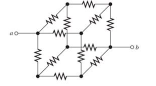
Problem 2.1P: Reduce each of the networks shown in Figure P2.1 to a single equivalent resistance by combining... Problem 2.2P: A 4- resistance is in series with the parallel combination of a 20- resistance and an unknown... Problem 2.3P: Find the equivalent resistance looking into terminals a and b in Figure P2.3. Figure P2.3 Problem 2.4P: Suppose that we need a resistance of 1.5 k and you have a box of 1-k resistors. Devise a network... Problem 2.5P: Find the equivalent resistance between terminals a and b in Figure P2.5. Figure P2.5 Problem 2.6P: Find the equivalent resistance between terminals a and b for each of the networks shown in Figure... Problem 2.7P: What resistance in parallel with 120 results in an equivalent resistance of 48 ? Problem 2.8P: Determine the resistance between terminals a and b for the network shown in Figure P2.8. Repeat... Problem 2.9P: Two resistances having values of R and 2R are in parallel R and the equivalent resistance are both... Problem 2.10P: A network connected between terminals a and b consists of two parallel combinations that are in... Problem 2.11P: Two resistances R1 and R2 are connected in parallel. We know that R1=90 and that the current... Problem 2.12P: Find the equivalent resistance for the infinite network shown in Figure P2.12(a). Because of its... Problem 2.13P: If we connect n 1000- resistances in parallel, what value is the equivalent resistance? Problem 2.14P: The heating element of an electric cook top has two resistive elements. R1=57.6 and R2=115.2 ,... Problem 2.15P: We are designing an electric space heater to operate from 120V. Two heating elements with... Problem 2.16P: Sometimes, we can use symmetry considerations to find the resistance of a circuit that cannot be... Problem 2.17P: The equivalent resistance between terminals a and b in Figure P2.17 is Rab=23 . Determine the value... Problem 2.18P: Three conductances G1 G2, and G3 are in series. Write an expression for the equivalent conductance... Problem 2.19P: Most sources of electrical power behave as (approximately) ideal voltage sources In this case, if we... Problem 2.20P: The resistance for the network shown in Figure P2.20 between terminals a and b with c open circuited... Problem 2.21P: Often, we encounter delta-connected loads such as that illustrated in Figure P2.21, in three-phase... Problem 2.22P: What are the steps in solving a circuit by network reduction (series/parallel combinations)? Does... Problem 2.23P: Find the values of i1 and i2 in Figure P2.23. Figure P2.23 Problem 2.24P: Find the voltages v1 and v2 for the circuit shown in Figure P2.24 by combining resistances in series... Problem 2.25P: Find the values of v and i in Figure P2.25. Figure P2.25 Problem 2.26P: Consider the circuit shown in Figure P2.24. Suppose that the value of vs is adjusted until v2=5 V.... Problem 2.27P: Find the voltage v and the currents i1 and 12 for the circuit shown in Figure P2.27. Figure P2.27 Problem 2.28P: Find the values of vs, v1, and i2 in Figure P2.28. Figure P2.28 Problem 2.29P: Find the values of i1 and i2 in Figure P2.29. Figure P2.29 Problem 2.30P: Consider the cirrcuit shown in Figure P2.30 Find the values of v1, v2, and vab. Figure P2.30 Problem 2.31P: Solve for the values of i1, i2, and the powers for the sources in Figure P2.31. Is the current... Problem 2.32P: The 12-V source in Figure P2.32 is delivering 36 mW of power. All four resistors have the same value... Problem 2.33P: Refer to the circuit shown in Figure P2.33. With the switch open, we have v2=8 V. On the other hand,... Problem 2.34P: Find the values of i1 and i2 in Figure P2.34. Find the power for each element in the circuit, and... Problem 2.35P: Find the values of i1 and i2 in Figure P2.35 Figure P2.35 Problem 2.36P: Use the voltage-division principle to calculate v1, v2, and v3 in Figure P2.36. Figure P2.36 Problem 2.37P: Use the current-division principle to calculate i1 and i2 in Figure P2.37. Figure P2.3 Problem 2.38P: Use the voltage-division principle to calculate vin Figure P2.38. Figure P2.38 Problem 2.39P: Use the current-division principle to calculate the value of in Figure P2.39. Figure P2.39 Problem 2.40P: Suppose we need to design a voltage-divider circuit to provide an output voltage vo=5 V from a 15-V... Problem 2.41P: A source supplies 120 V to the series combination of a 10- resistance, a 5- resistance, and an... Problem 2.42P: We have a 60- resistance, a 20- resistance, and an unknown resistance Rx in parallel with a 15 mA... Problem 2.43P: A worker is standing on a wet concrete floor, holding an electric drill having a metallic case. The... Problem 2.44P: Suppose we have a load that absorbs power and requires a current varying between 0 and 50 mA. The... Problem 2.45P: We have a load resistance of 50 that we wish to supply with 5 V. A 12.6-V voltage source and... Problem 2.46P: We have a load resistance of 1 k that we wish to supply with 25 mW. A 20-mA current source and... Problem 2.47P: The circuit of Figure P2.47 is similar to networks used en digital-to-analog converters. For this... Problem 2.48P: Write equations and solve for the node voltages shown in Figure P2.48. Then, find the value of i1 .... Problem 2.49P: Solve for the node voltages shown in Figure P2.49. Then, find the value of is. Figure P2.49 Problem 2.50P: Solve for the node voltages shown in Figure P2.50. What are the new values of the node voltages... Problem 2.51P: Given R1=4 , R2=5 , R2=8 , R4=10 , R5=2 , and i5=2A , solve for the node voltages shown in Figure... Problem 2.52P: Determine the value of i1 in Figure P2.52 using node voltages to solve the circuit. Select the... Problem 2.53P: Given R1=15 , R5=5 , R3=20 , R4=10 , R5=8 , R6=4 , and is=5A, solve for the node voltages shown in... Problem 2.54P: In solving a network, what rule must you observe when writing KCL equations? Why? Problem 2.55P: Use the symbolic features of MATLAB to find an expression for the equivalent resistance for the... Problem 2.56P: Solve for the values of the node voltages shown in Figure P2.56. Then, find the value of ix. Figure... Problem 2.57P: Solve for the node voltages shown in Figure P2.57. Figure P2.57 Problem 2.58P: Solve for the power delivered to the 8- resistance and for the node voltages shown in Figure P2.58.... Problem 2.59P: Solve for the node voltages shown in Figure P2.59. Figure P2.59 Problem 2.60P: Find the equivalent resistance looking into terminals for the network shown in Figure P2.60. [Hint:... Problem 2.61P: Find the equivalent resistance looking into terminals for the network shown in Figure P2.61. [Hint:... Problem 2.62P: Figure P2.62 shows an unusual voltage-divider circuit Use node-voltage analysis and the symbolic... Problem 2.63P: Solve for the node voltages in the circuit of Figure P2.63. Disregard the mesh currents, i1, i2, i3,... Problem 2.64P: We have a cube with 1- resistances along each edge as illustrated in Figure P2.64 in which we are... Problem 2.65P: Solve for the power delivered to the 15- resistor and for the mesh currents shown in Figure P2.65.... Problem 2.66P: Determine the value of v2 and the power delivered by the source in the circuit of Figure P2.24 by... Problem 2.67P: Use mesh-current analysis to find the value of i1 in the circuit of Figure P2.48. Problem 2.68P: Solve for the power delivered by the voltage source in Figure P2.68, using the mesh-current method.... Problem 2.69P: Use mesh-current analysis to find the value of v in the circuit of Figure P2.38. Problem 2.70P: Use mesh-current analysis to find the value of i3 in the circuit of Figure P2.39. Problem 2.71P: Use mesh-current analysis to find the values of i1 and i2 in Figure P2.27. Select i1 clockwise... Problem 2.72P: Find the power delivered by the source and the values of i1 and i2 in the circuit of Figure P2.23,... Problem 2.73P: Use mesh-current analysis to find the values of i1 and i2 in Figure P2.29 First, select iA clockwise... Problem 2.74P: Use mesh-current analysis to find the values of i1 and i2 in Figure P2.28. First, selectiAclockwise... Problem 2.75P: The circuit shown in Figure P2.75 is the dc equivalent of a simple residential power distribution... Problem 2.76P: Use MATLAB and mesh-current analysis to determine the value of v3 in the circuit of Figure P2.51.... Problem 2.77P: Connect a 1-V voltage source across terminals a and b of the network shown in Figure P2.55. Then,... Problem 2.78P: Connect a 1-V voltage source across the terminals of the network shown in Figure P2.1(a). Then,... Problem 2.79P: Use MATLAB to solve for the mesh currents in Figure P2.63. Problem 2.80P: Find the Thévenin and Norton equivalent circuits for the two-terminal circuit shown in Figure P2.80.... Problem 2.81P: We can model a certain battery as a voltage source in series with a resistance The open-circuit... Problem 2.82P: Find the Thévenin and Norton equivalent circuits for the circuit shown in Figure P2.82. Figure P2.82 Problem 2.83P: Find the Thévenin and Norton equivalent circuits for the two-terminal circuit shown in Figure P2.83.... Problem 2.84P: Find the Thévenin arid Norton equivalent circuits for the circuit shown in Figure P2.84. Take care... Problem 2.85P: An automotive battery has an open-circuit voltage of 12.6 V and supplies 100 A when a 0.1- ... Problem 2.86P: A certain two-terminal circuit has an open-circuit voltage of 15 V. When a 2-k load is attached,... Problem 2.87P: If we measure the voltage at the terminals of a two-terminal netwod with two known (and different)... Problem 2.88P: Find the Thévenin and Norton equivalent circuits for the circuit shown in Figure P2.88. Figure P2.88 Problem 2.89P: Find the maximum power that can be delivered to a resistive load by the circuit shown in Figure... Problem 2.90P: Find the maximum power that can be delivered to a resistive load by the circuit shown in Figure... Problem 2.91P: Figure P2.91 shows a resistive load RL connected to a Thévenin equivalent circuit. For what value of... Problem 2.92P: Starling from the Norton equivalent circuit with a resistive load RL attached, find an expression... Problem 2.93P: A battery can be modeled by a voltage source Vt in series with a resistance Rt. Assuming that the... Problem 2.94P: Use superposition to find the current i in Figure P2.94. First, zero the current source and find the... Problem 2.95P: Solve for is in Figure P2.49 by using superposition. Problem 2.96P: Solve the circuit shown in Figure P2.48 by using superposition First, zero the 1-A source and find... Problem 2.97P: Solve for i1 in Figure P2.34 by using superposition. Problem 2.98P: Another method of solving the circuit of Figure P2.24 is to start by assuming that v2=1 V.... Problem 2.99P: Use the method of Problem P2.98 for the circuit of Figure P2.23 starting with the assumption that... Problem 2.100P: Solve for the actual value of i6 for the circuit of Figure P2.100, starting with the assumption that... Problem 2.101P: Device A shown in Figure P2.101 has v=3i2 for i 0 and v=0 for i<0. Figure P2.101 Solve for V with... Problem 2.102P: The Wheatstone bridge shown in Figure 2.66 is balanced with R1=10 k , R3=3419 , and R2=1 k Find... Problem 2.103P: The Wheatstone bridge shown in Figure 2.66has vs=10 V,R1=10 k ,R2=10 k , and Rx=5932 . The... Problem 2.104P: In theory, any values can be used for R1 and R3 in the Wheatstone bridge of Figure 2.66. For the... Problem 2.105P: Derive expressions for the Thévenin voltage and resistance seen by the detector in the Wheatstone... Problem 2.106P: Derive Equation 2.93 for the bridge circuit of Figure 2.67 on page 109. Problem 2.107P Problem 2.108P: Explain what would happen if, in wiring the bridge circuit of Figure 2.67 on page 10? Explain what... Problem 2.1PT: Match each entry in Table T2.1(a) with the best choice from the list given in Table T2.1(b) for... Problem 2.2PT: Consider the circuit of Figure T2.2 with vs=96V , R1=6 , R2=48 , R3=16 , and R4=60 . Determine the... Problem 2.3PT: Write MATLAB code to solve for the node voltages for the circuit of Figure T2.3 Figure T2.3 Problem 2.4PT: Write a set of equations that can be used to solve for the mesh currents of Figure 12.4. Be sure to... Problem 2.5PT: Determine the Thévenin and Norton equivalent circuits for the circuit of Figure T2.5 Draw the... Problem 2.6PT: According to the superposition principle, what percentage of the total current flowing through the... Problem 2.7PT: Determine the equivalent resistance between terminals a and b in Figure T2.7. Figure T2.7 Problem 2.8PT: Transform the 2-A current source and 6- resistance in Figure T2.8 into an equivalent series... format_list_bulleted


 Introductory Circuit Analysis (13th Edition)Electrical EngineeringISBN:9780133923605Author:Robert L. BoylestadPublisher:PEARSON
 Delmar's Standard Textbook Of ElectricityElectrical EngineeringISBN:9781337900348Author:Stephen L. HermanPublisher:Cengage Learning
 Programmable Logic ControllersElectrical EngineeringISBN:9780073373843Author:Frank D. PetruzellaPublisher:McGraw-Hill Education
 Fundamentals of Electric CircuitsElectrical EngineeringISBN:9780078028229Author:Charles K Alexander, Matthew SadikuPublisher:McGraw-Hill Education
 Electric Circuits. (11th Edition)Electrical EngineeringISBN:9780134746968Author:James W. Nilsson, Susan RiedelPublisher:PEARSON
 Engineering ElectromagneticsElectrical EngineeringISBN:9780078028151Author:Hayt, William H. (william Hart), Jr, BUCK, John A.Publisher:Mcgraw-hill Education,