
Concept explainers
Videos
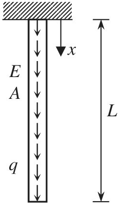
A bar in the figure is under the uniformly distributed load q due to gravity. For a linear elastic material with Young’s modulus E and uniform cross-sectional area A, the governing differential equation can be written as
a. Starting from the above differential equation, derive an integral equation using the Galerkin method.
b. Write the expression of boundary conditions at
c. Derive the assembled finite element matrix equation, and solve it after applying boundary conditions.
Want to see the full answer?
Check out a sample textbook solution
Chapter 2 Solutions
Introduction To Finite Element Analysis And Design


- Q | Sign in PDE Lecture W09.pdf PDF MMB241 - Tutorial L9.pdi X PDF MMB241 - Tutorial L10.p X PDF MMB241 - Tutorial L11.p X Lecture W12-Work and X + File C:/Users/KHULEKANI/Desktop/mmb241/Lecture%20W12%20-%20Work%20and%20Energy.pdf ||! Draw | IA | a | Ask Copilot Class Work + 33 of 34 D Question 1 The engine of a 3500-N car is generating a constant power of 50 hp (horsepower) while the car is traveling up the slope with a constant speed. If the engine is operating with an efficiency of € 0.8, determine the speed of the car. Neglect drag and rolling resistance. Use g 9.81 m/s² and 1 hp = 745.7 W. 10 го Question 2 A man pushes on a 60-N crate with a force F. The force is always directed downward at an angle of 30° from the horizontal, as shown in the figure. The magnitude of the force is gradually increased until the crate begins to slide. Determine the crate's initial acceleration once it starts to move. Assume the coefficient of static friction is μ = 0.6, the coefficient of kinetic…arrow_forwardstate is Derive an expression for the volume expansivity of a substance whose equation of RT P = v-b a v(v + b)TZ where a and b are empirical constants.arrow_forwardFor a gas whose equation of state is P(v-b)=RT, the specified heat difference Cp-Cv is equal to which of the following (show all work): (a) R (b) R-b (c) R+b (d) 0 (e) R(1+v/b)arrow_forward
- of state is Derive an expression for the specific heat difference of a substance whose equation RT P = v-b a v(v + b)TZ where a and b are empirical constants.arrow_forwardTemperature may alternatively be defined as T = ди v Prove that this definition reduces the net entropy change of two constant-volume systems filled with simple compressible substances to zero as the two systems approach thermal equilibrium.arrow_forwardUsing the Maxwell relations, determine a relation for equation of state is (P-a/v²) (v−b) = RT. Os for a gas whose av Tarrow_forward
- (◉ Homework#8arrow_forwardHomework#8arrow_forwardBox A has a mass of 15 kilograms and is attached to the 20 kilogram Box B using the cord and pulley system shown. The coefficient of kinetic friction between the boxes and surface is 0.2 and the moment of inertia of the pulley is 0.5 kg * m^ 2. After 2 seconds, how far do the boxes move? A бро Barrow_forwardBox A has a mass of 15 kilograms and is attached to the 20 kilogram Box B using the cord and pulley system shown. The coefficient of kinetic friction between the boxes and surface is 0.2 and the moment of inertia of the pulley is 0.5 kg * m^2. Both boxes are 0.25 m long and 0.25 m high. The cord is attached to the bottom of Box A and the middle of box B. After 2 seconds, how far do the boxes move? A From бро Barrow_forwardarrow_back_iosSEE MORE QUESTIONSarrow_forward_iosRecommended textbooks for you
 Principles of Heat Transfer (Activate Learning wi...Mechanical EngineeringISBN:9781305387102Author:Kreith, Frank; Manglik, Raj M.Publisher:Cengage Learning
Principles of Heat Transfer (Activate Learning wi...Mechanical EngineeringISBN:9781305387102Author:Kreith, Frank; Manglik, Raj M.Publisher:Cengage Learning