
Vector Mechanics for Engineers: Statics and Dynamics
12th Edition
ISBN: 9781259638091
Author: Ferdinand P. Beer, E. Russell Johnston Jr., David Mazurek, Phillip J. Cornwell, Brian Self
Publisher: McGraw-Hill Education
expand_more
expand_more
format_list_bulleted
Videos
Textbook Question
Chapter 16.1, Problem 16.15P
At the instant shown, the tensions in the vertical ropes AB and DE are 300 N and 200 N, respectively. Knowing that the mass of the uniform bar BE is 5 kg, determine, at this instant, (a) the force P, (b) the magnitude of the angular velocity of each rope, (c) the angular acceleration of each rope.
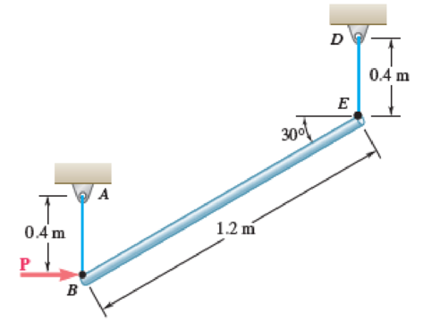
Fig. P16.15
Expert Solution & Answer
Want to see the full answer?
Check out a sample textbook solution
Students have asked these similar questions
(a) Find a second-order homogeneous linear ODE for which the given functions are
solutions. (b) Show linear independence by the Wronskian. (c) Solve the initial value
problem.
a. cos(5x), sin(5x), y(0) = 3, y'(0) = −5
b. e-2.5x cos(0.3x), e-2.5x sin(0.3x), y(0) = 3, y'(0) = -7.5
Solve the IVP.
a. y" 16y 17e* ;
=
y(0) = 6,
y'(0) = -2
b. (D² + 41)y = sin(t) + ½ sin(3t) + sin(t) ; y(0) = 0, y'(0) :
=
35
31
Find the general solution.
a. y' 5y = 3ex - 2x + 1
-
b. y" +4y' + 4y = e¯*cos(x)
c. (D² + I)y = cos(wt), w² # 1
Chapter 16 Solutions
Vector Mechanics for Engineers: Statics and Dynamics
Ch. 16.1 - Two pendulums, A and B, with the masses and...Ch. 16.1 - Two pendulums, A and B, with the masses and...Ch. 16.1 - Two solid cylinders, A and B, have the same mass m...Ch. 16.1 - Prob. 16.1FBPCh. 16.1 - Prob. 16.2FBPCh. 16.1 - Prob. 16.3FBPCh. 16.1 - The 400-lb crate shown is lowered by means of two...Ch. 16.1 - A 60-lb uniform thin panel is placed in a truck...Ch. 16.1 - A 60-lb uniform thin panel is placed in a truck...Ch. 16.1 - A loading car is at rest on a track forming an...
Ch. 16.1 - A 2100-lb rear-wheel-drive tractor carries a 900...Ch. 16.1 - A uniform rod BC of mass 4 kg is connected to a...Ch. 16.1 - A 2000-kg truck is being used to lift a 400-kg...Ch. 16.1 - The support bracket shown is used to transport a...Ch. 16.1 - Prob. 16.8PCh. 16.1 - A 20-kg cabinet is mounted on casters that allow...Ch. 16.1 - Solve Prob. 16.9, assuming that the casters are...Ch. 16.1 - Prob. 16.11PCh. 16.1 - Prob. 16.12PCh. 16.1 - The retractable shelf shown is supported by two...Ch. 16.1 - Bars AB and BE, each with a mass of 4 kg, are...Ch. 16.1 - At the instant shown, the tensions in the vertical...Ch. 16.1 - Three bars, each of mass 3 kg, are welded together...Ch. 16.1 - Members ACE and DCB are each 600 mm long and are...Ch. 16.1 - A prototype rotating bicycle rack is designed to...Ch. 16.1 - The control rod AC is guided by two pins that...Ch. 16.1 - The coefficients of friction between the 30-lb...Ch. 16.1 - Prob. 16.21PCh. 16.1 - Prob. 16.22PCh. 16.1 - For a rigid body in translation, show that the...Ch. 16.1 - For a rigid body in centroidal rotation, show that...Ch. 16.1 - It takes 10 min for a 2.4-Mg flywheel to coast to...Ch. 16.1 - The rotor of an electric motor has an angular...Ch. 16.1 - The 10-in.-radius brake drum is attached to a...Ch. 16.1 - The 10-in.-radius brake drum is attached to a...Ch. 16.1 - The 100-mm-radius brake drum is attached to a...Ch. 16.1 - The 180-mm-radius disk is at rest when it is...Ch. 16.1 - Solve Prob. 16.30, assuming that the direction of...Ch. 16.1 - In order to determine the mass moment of inertia...Ch. 16.1 - The flywheel shown has a radius of 20 in., a...Ch. 16.1 - Each of the double pulleys shown has a mass moment...Ch. 16.1 - Two disks A and B, of mass mA = 2 kg and mB = 4...Ch. 16.1 - Two disks A and B, of mass mA = 2 kg and mB = 4...Ch. 16.1 - Gear A weighs 1 lb and has a radius of gyration of...Ch. 16.1 - The 25-lb double pulley shown is at rest and in...Ch. 16.1 - A belt of negligible mass passes between cylinders...Ch. 16.1 - Prob. 16.40PCh. 16.1 - Disk A has a mass of 6 kg and an initial angular...Ch. 16.1 - Prob. 16.42PCh. 16.1 - Disk A has a mass mA = 4 kg, a radius rA = 300 mm,...Ch. 16.1 - Disk B is at rest when it is brought into contact...Ch. 16.1 - Prob. 16.45PCh. 16.1 - Prob. 16.46PCh. 16.1 - For a rigid body in plane motion, show that the...Ch. 16.1 - A uniform slender rod AB rests on a frictionless...Ch. 16.1 - Prob. 16.49PCh. 16.1 - Prob. 16.50PCh. 16.1 - Prob. 16.51PCh. 16.1 - A 250-lb satellite has a radius of gyration of 24...Ch. 16.1 - A rectangular plate of mass 5 kg is suspended from...Ch. 16.1 - Prob. 16.54PCh. 16.1 - A drum with a 200-mm radius is attached to a disk...Ch. 16.1 - A drum with a 200-mm radius is attached to a disk...Ch. 16.1 - The 12-lb uniform disk shown has a radius of r =...Ch. 16.1 - Prob. 16.58PCh. 16.1 - Prob. 16.59PCh. 16.1 - 16.60 and 16.61The 400-lb crate shown is lowered...Ch. 16.1 - Prob. 16.61PCh. 16.1 - Two uniform cylinders, each of weight W = 14 lb...Ch. 16.1 - Prob. 16.63PCh. 16.1 - Prob. 16.64PCh. 16.1 - A uniform slender bar AB with a mass m is...Ch. 16.1 - Prob. 16.66PCh. 16.1 - 16.66 through 16.68A thin plate of the shape...Ch. 16.1 - 16.66 through 16.68A thin plate of the shape...Ch. 16.1 - A sphere of radius r and mass m is projected along...Ch. 16.1 - Solve Prob. 16.69, assuming that the sphere is...Ch. 16.1 - A bowler projects an 8-in.-diameter ball weighing...Ch. 16.1 - Prob. 16.72PCh. 16.1 - A uniform sphere of radius r and mass m is placed...Ch. 16.1 - A sphere of radius r and mass m has a linear...Ch. 16.2 - A cord is attached to a spool when a force P is...Ch. 16.2 - Prob. 16.5CQCh. 16.2 - Prob. 16.6CQCh. 16.2 - Prob. 16.7CQCh. 16.2 - Prob. 16.5FBPCh. 16.2 - Two identical 4-lb slender rods AB and BC are...Ch. 16.2 - Prob. 16.7FBPCh. 16.2 - Prob. 16.8FBPCh. 16.2 - Show that the couple I of Fig. 16.15 can be...Ch. 16.2 - A uniform slender rod of length L = 900 mm and...Ch. 16.2 - A crate of mass 80 kg is held in the position...Ch. 16.2 - A uniform slender rod of length L = 36 in. and...Ch. 16.2 - In Prob. 16.78, determine (a) the distance h for...Ch. 16.2 - An athlete performs a leg extension on a machine...Ch. 16.2 - Prob. 16.81PCh. 16.2 - A turbine disk weighing 50 lb rotates at a...Ch. 16.2 - The 80-lb tailgate of a car is supported by the...Ch. 16.2 - A uniform rod of length L and mass m is supported...Ch. 16.2 - Three stage lights are mounted on a pipe fixture...Ch. 16.2 - An adapted launcher uses a torsional spring about...Ch. 16.2 - A 4-kg slender rod is welded to the edge of a 3-kg...Ch. 16.2 - Prob. 16.88PCh. 16.2 - The object ABC consists of two slender rods welded...Ch. 16.2 - A 3.5-kg slender rod AB and a 2-kg slender rod BC...Ch. 16.2 - A 9-kg uniform disk is attached to the 5-kg...Ch. 16.2 - Derive the equation MC=IC for the rolling disk of...Ch. 16.2 - Prob. 16.93PCh. 16.2 - Prob. 16.94PCh. 16.2 - Prob. 16.95PCh. 16.2 - Prob. 16.96PCh. 16.2 - A 40-kg flywheel of radius R = 0.5 m is rigidly...Ch. 16.2 - Prob. 16.98PCh. 16.2 - 16.98 through 16.101A drum of 80-mm radius is...Ch. 16.2 - 16.98 through 16.101A drum of 80-mm radius is...Ch. 16.2 - 16.98 through 16.101A drum of 80-mm radius is...Ch. 16.2 - 16.102 through 16.105A drum of 4-in. radius is...Ch. 16.2 - 16.102 through 16.105A drum of 4-in. radius is...Ch. 16.2 - 16.102 through 16.105A drum of 4-in. radius is...Ch. 16.2 - 16.102 through 16.105A drum of 4-in. radius is...Ch. 16.2 - 16.106 and 16.107A 12-in.-radius cylinder of...Ch. 16.2 - 16.106 and 16.107A 12-in.-radius cylinder of...Ch. 16.2 - Gear C has a mass of 5 kg and a centroidal radius...Ch. 16.2 - Two uniform disks A and B, each with a mass of 2...Ch. 16.2 - A single-axis personal transport device starts...Ch. 16.2 - A hemisphere of weight W and radius r is released...Ch. 16.2 - A hemisphere of weight W and radius r is released...Ch. 16.2 - The center of gravity G of a 1.5-kg unbalanced...Ch. 16.2 - A small clamp of mass mB is attached at B to a...Ch. 16.2 - Prob. 16.115PCh. 16.2 - A 4-lb bar is attached to a 10-lb uniform cylinder...Ch. 16.2 - The uniform rod AB with a mass m and a length of...Ch. 16.2 - Prob. 16.118PCh. 16.2 - Prob. 16.119PCh. 16.2 - Prob. 16.120PCh. 16.2 - End A of the 6-kg uniform rod AB rests on the...Ch. 16.2 - End A of the 6-kg uniform rod AB rests on the...Ch. 16.2 - End A of the 8-kg uniform rod AB is attached to a...Ch. 16.2 - The 4-kg uniform rod ABD is attached to the crank...Ch. 16.2 - The 3-lb uniform rod BD is connected to crank AB...Ch. 16.2 - The 3-lb uniform rod BD is connected to crank AB...Ch. 16.2 - The test rig shown was developed to perform...Ch. 16.2 - Solve Prob. 16.127 for = 90. 16.127The test rig...Ch. 16.2 - The 4-kg uniform slender bar BD is attached to bar...Ch. 16.2 - The motion of the uniform slender rod of length L...Ch. 16.2 - At the instant shown, the 20-ft-long, uniform...Ch. 16.2 - A driver starts his car with the door on the...Ch. 16.2 - Prob. 16.133PCh. 16.2 - The hatchback of a car is positioned as shown to...Ch. 16.2 - The 6-kg rod BC connects a 10-kg disk centered at...Ch. 16.2 - Prob. 16.136PCh. 16.2 - In the engine system shown, l = 250 mm and b = 100...Ch. 16.2 - Solve Prob. 16.137 when = 90. 16.137In the engine...Ch. 16.2 - The 4-lb uniform slender rod AB, the 8-lb uniform...Ch. 16.2 - The 4-lb uniform slender rod AB, the 8-lb uniform...Ch. 16.2 - Two rotating rods in the vertical plane are...Ch. 16.2 - Two rotating rods in the vertical plane are...Ch. 16.2 - Two disks, each with a mass m and a radius r, are...Ch. 16.2 - A uniform slender bar AB of mass m is suspended as...Ch. 16.2 - A uniform rod AB, of mass 15 kg and length 1 m, is...Ch. 16.2 - The uniform slender 2-kg bar BD is attached to the...Ch. 16.2 - Prob. 16.147PCh. 16.2 - Prob. 16.148PCh. 16.2 - Prob. 16.149PCh. 16.2 - Prob. 16.150PCh. 16.2 - (a) Determine the magnitude and the location of...Ch. 16.2 - Prob. 16.152PCh. 16 - A cyclist is riding a bicycle at a speed of 20 mph...Ch. 16 - The forklift truck shown weighs 3200 lb and is...Ch. 16 - The total mass of the Baja car and driver,...Ch. 16 - Identical cylinders of mass m and radius r are...Ch. 16 - Prob. 16.157RPCh. 16 - The uniform rod AB of weight W is released from...Ch. 16 - Prob. 16.159RPCh. 16 - Prob. 16.160RPCh. 16 - A cylinder with a circular hole is rolling without...Ch. 16 - Two 3-kg uniform bars are connected to form the...Ch. 16 - A crate of mass 80 kg is held in the position...Ch. 16 - The Geneva mechanism shown is used to provide an...
Additional Engineering Textbook Solutions
Find more solutions based on key concepts
What output will the following lines of code display on the screen? cout "The works of Wolfgang\ninclude the f...
Starting Out with C++: Early Objects (9th Edition)
A nozzle at A discharges water with an initial velocity of 36 ft/s at an angle with the horizontal. Determine ...
Vector Mechanics For Engineers
Computers process data under the control of sets of instructions called
Java How to Program, Early Objects (11th Edition) (Deitel: How to Program)
How is the hydrodynamic entry length defined for flow in a pipe? Is the entry length longer in laminar or turbu...
Fluid Mechanics: Fundamentals and Applications
1.2 Explain the difference between geodetic and plane
surveys,
Elementary Surveying: An Introduction To Geomatics (15th Edition)
What is an uninitialized variable?
Starting Out with Programming Logic and Design (5th Edition) (What's New in Computer Science)
Knowledge Booster


Learn more about
Need a deep-dive on the concept behind this application? Look no further. Learn more about this topic, mechanical-engineering and related others by exploring similar questions and additional content below.Similar questions
- handwritten solutions, please!!arrow_forward> Homework 4 - Spring 2025.pdf Spring 2025.pdf k 4 - Spring 2025.pdf (447 KB) Due: Thursday, February 27 Page 1 > of 2 ZOOM 1. A simply supported shaft is shown in Figure 1 with wo = 25 N/cm and M = 20 N cm. Use singularity functions to determine the reactions at the supports. Assume EI = 1000 kN cm². M Wo 0 10 20 30 40 50 60 70 80 90 100 110 cm Figure 1 - Problem 1 2. A support hook was formed from a rectangular bar. Find the stresses at the inner and outer surfaces at sections just above and just below O-B. 210 mmarrow_forwardA distillation column with a total condenser and a partial reboiler is separating ethanol andwater at 1.0 atm. Feed is 0.32 mol fraction ethanol and it enters as a saturated liquid at 100mol/s on the optimum plate. The distillate product is a saturated liquid with 80 mol% ethanol.The condenser removes 5615 kW. The bottoms product is 0.05 mol fraction ethanol. AssumeCMO is valid.(a) Find the number of equilibrium stages for this separation. [6 + PR](b) Find how much larger the actual reflux ratio, R, used is than Rmin, i.e. R/Rmin. [3]Note: the heats of vaporization of ethanol and water are λe = 38.58 and λw = 40.645 arrow_forward
- We have a feed that is a binary mixture of methanol and water (60.0 mol% methanol) that issent to a system of two flash drums hooked together. The vapor from the first drum is cooled,which partially condenses the vapor, and then is fed to the second flash drum. Both drumsoperate at 1.0 atm and are adiabatic. The feed to the first drum is 1000 kmol/hr. We desire aliquid product from the first drum that is 35.0 mol% methanol. The second drum operates at afraction vaporized of (V/F)2 = 0.25.(a) Find the liquid flow rate leaving the first flash drum, L1 (kmol/hr). [286 kmol/hr](b) Find the vapor composition leaving the second flash drum, y2. [0.85]arrow_forward= The steel curved bar shown has rectangular cross-section with a radial height h = 6 mm and thickness b = 4mm. The radius of the centroidal axis is R = 80 mm. A force P = 10 N is applied as shown. Assume the steel modulus of 207,000 MPa and G = 79.3(103) MPa, repectively. elasticity and shear modulus E = Find the vertical deflection at point B. Use Castigliano's method for a curved flexural member and since R/h > 10, neglect the effect of shear and axial load, thereby assuming that deflection is due to merely the bending moment. Note the inner and outer radii of the curves bar are: r = 80 + ½ (6) = 83 mm, r₁ = 80 − ½ (6) = 77 mm 2 2 Sπ/2 sin² 0 d = √π/² cos² 0 d0 = Π 0 4 大 C R B Parrow_forwardThe steel eyebolt shown in the figure is loaded with a force F = 75 lb. The eyebolt is formed from round wire of diameter d = 0.25 in to a radius R₁ = 0.50 in in the eye and at the shank. Estimate the stresses at the inner and outer surfaces at section A-A. Notice at the section A-A: r₁ = 0.5 in, ro = 0.75 in rc = 0.5 + 0.125 = 0.625 in Ri 200 F FAarrow_forward
- I have the fallowing question and solution from a reeds naval arc book. Im just confused as to where this answer came from and the formulas used. Wondering if i could have this answer/ solution broken down and explained in detail. A ship of 7000 tonne displacement has a waterplane areaof 1500 m2. In passing from sea water into river water of1005 kg/m3 there is an increase in draught of 10 cm. Find the Idensity of the sea water. picture of the "answer" is attachedarrow_forwardProblem A2 long steel tube has a rectangular cross-section with outer dimensions of 20 x 20 mm and a uniform wall thickness of 2. The tube is twisted along its length with torque, T. The tube material is 1045 CD steel with shear yield strength of S,, =315 MPa. Assume shear modulus, G = 79.3GPa. (a) Estimate the maximum torque that can be applied without yielding (b) Estimate the torque required to produce 5 degrees total angle of twist over the length of the tube. (c) What is the maximum torque that can be applied without yielding, if a solid rectangular shaft with dimensions of 20 x 20 is used? You may use the exact solution.arrow_forwardA simply supported beam is loaded as shown. Considering symmetry, the reactions at supports A and B are R₁ = R₂ = wa 2 Using the singularity method, determine the shear force V along the length of the beam as a function of distance x from the support A. A B Ir. 2a За W C R₁₂ x 2. Using the singularity method, determine the bending M along the length of the beam as a function of distance x, from the support A. 3. Using the singularity method, determine the beam slope and deflection along the length of the beam as a function of the distance x, from the support A. Assume the material modulus of elasticity, E and the moment of inertia of the beam cross-section, I are given.arrow_forward
- A steel tube, 2 m long, has a rectangular cross-section with outer dimensions of 20 × 30 mm and a uniform wall thickness of 1 mm. The tube is twisted along its length with torque, T. The tube material is 1018 CD steel with shear yield strength of Ssy =185 MPa. Assume shear modulus, G = 79.3GPa. (a) Estimate the maximum torque that can be applied without yielding.- (b) Estimate the torque required to produce 3 degrees total angle of twist over the length of the tube. (c) What is the maximum torque that can be applied without yielding, if a solid rectangular shaft with dimensions of 20 x 30 mm is used? You may use the exact solution:arrow_forward|The typical cruising altitude of a commercial jet airliner is 10,700 m above sea level where the local atmospheric temperature is 219 K, and the pressure is 0.25 bar. The aircraft utilizes a cold air-standard Brayton cycle as shown with a volume flow rate of 1450 m³/s. The compressor pressure ratio is 50, and the maximum cycle temperature is 1700 K. The compressor and turbine isentropic efficiencies are 90%. Neglect kinetic and potential energy effects in this problem. Assume constant specific heats with k=1.4, Ra=0.287 kJ/kg- K, Cp=1.0045 kJ/kg-K, and cv = 0.7175 kJ/kg-K. a) Draw a T-s diagram for this cycle on the diagram provided. b) Fill in the table below with the missing information. T[K] Heat exchanger Heat exchanger State P [bar] 1 0.25 2s 2 3 4s 4 Turbine c) (5pts) Determine the inlet air density in [kg/m³] (at state 1), and the system mass flowrate in [kg/s]. d) (10pts) Determine the net power developed in [MW]. Be sure to draw each component you are analyzing, define the…arrow_forwardOn the axis provide, draw a corresponding T-s diagram for the Brayton cycle shown given the following information: iv. V. vi. Compressor 1 is reversible, but Compressor 2 and the turbine are irreversible. The pressure drops through the regenerator are combustors are negligible. The pressures at state (1) and state (10) are equal to the atmospheric pressure. T 8 Regenerator fmm mmm Qin Combustor Compressor Compressor Turbine W cycle Intercooler mm Courarrow_forward
arrow_back_ios
SEE MORE QUESTIONS
arrow_forward_ios
Recommended textbooks for you
 Elements Of ElectromagneticsMechanical EngineeringISBN:9780190698614Author:Sadiku, Matthew N. O.Publisher:Oxford University Press
 Mechanics of Materials (10th Edition)Mechanical EngineeringISBN:9780134319650Author:Russell C. HibbelerPublisher:PEARSON
 Thermodynamics: An Engineering ApproachMechanical EngineeringISBN:9781259822674Author:Yunus A. Cengel Dr., Michael A. BolesPublisher:McGraw-Hill Education
 Control Systems EngineeringMechanical EngineeringISBN:9781118170519Author:Norman S. NisePublisher:WILEY
 Mechanics of Materials (MindTap Course List)Mechanical EngineeringISBN:9781337093347Author:Barry J. Goodno, James M. GerePublisher:Cengage Learning
 Engineering Mechanics: StaticsMechanical EngineeringISBN:9781118807330Author:James L. Meriam, L. G. Kraige, J. N. BoltonPublisher:WILEY
Elements Of Electromagnetics
Mechanical Engineering
ISBN:9780190698614
Author:Sadiku, Matthew N. O.
Publisher:Oxford University Press
Mechanics of Materials (10th Edition)
Mechanical Engineering
ISBN:9780134319650
Author:Russell C. Hibbeler
Publisher:PEARSON
Thermodynamics: An Engineering Approach
Mechanical Engineering
ISBN:9781259822674
Author:Yunus A. Cengel Dr., Michael A. Boles
Publisher:McGraw-Hill Education
Control Systems Engineering
Mechanical Engineering
ISBN:9781118170519
Author:Norman S. Nise
Publisher:WILEY
Mechanics of Materials (MindTap Course List)
Mechanical Engineering
ISBN:9781337093347
Author:Barry J. Goodno, James M. Gere
Publisher:Cengage Learning
Engineering Mechanics: Statics
Mechanical Engineering
ISBN:9781118807330
Author:James L. Meriam, L. G. Kraige, J. N. Bolton
Publisher:WILEY
Mechanical SPRING DESIGN Strategy and Restrictions in Under 15 Minutes!; Author: Less Boring Lectures;https://www.youtube.com/watch?v=dsWQrzfQt3s;License: Standard Youtube License